Table of Contents
What is the minimum frequency signal that can be generated in PIC18F4550 microcontroller?
What is the minimum frequency signal that can be generated in PIC18F4550 microcontroller? This will help us to determine frequency while designing many applications. To answer this question first we need to know either we are using 16 bit mode or 8 bit mode of programming. In this article we will study about 16-bit mode and then we can map it to 8-bit mode of operation. Since we know that in 16 bit timer mode, the values can vary from 0000H to FFFFH. So, in order to find the minimum frequency we need maximum time delay to be introduced as there is inverse relation between time and frequency. The minimum value is 0000H.
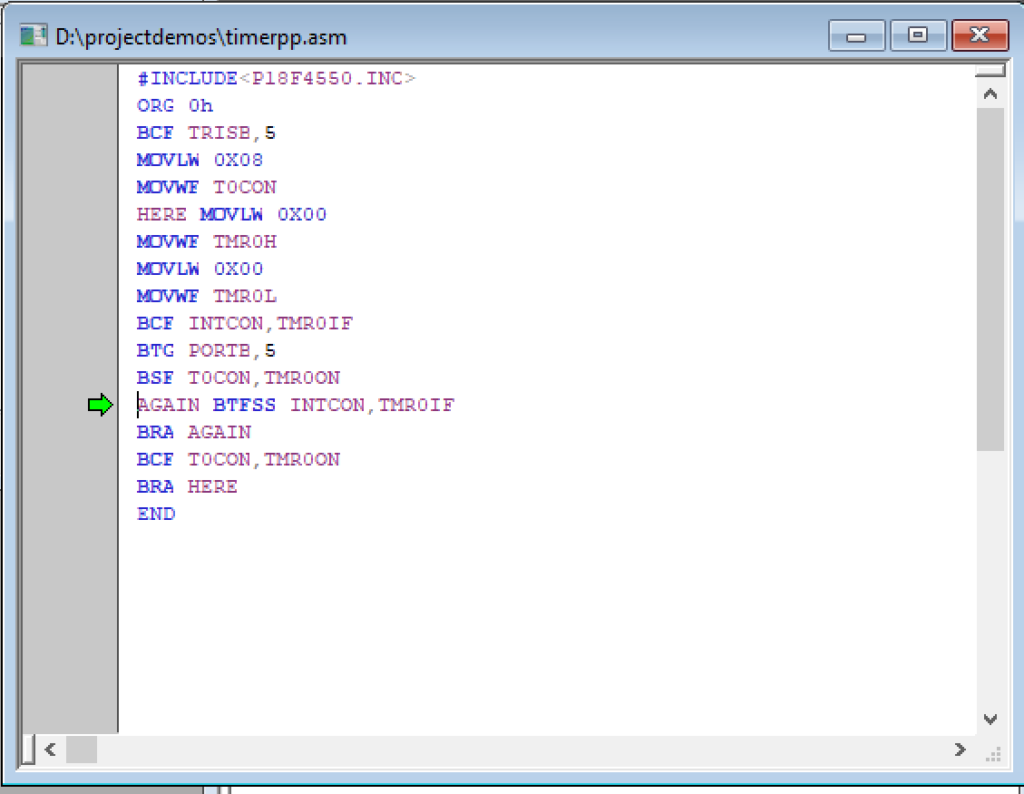
Following steps are used for generating a square waveform of 50% duty cycle with minimum possible frequency.
- Load TMR0H:TMR0L=0000
- start the timer
- keep monitoring TMR0IF until it becomes high.
- As TMR0IF is set, stop the timer.
- Clear the TMR0IF
- Reload timers registers again
- and repeat step 2
Calculations for minimum frequency signal.
Since timer register has 0000H so subtract it from
65536-0000=65536
If 10Mhz crystal oscillator is used for providing the clock signal then it divides the crystal frequency with 4 which gives=10MHz/4=2.5MHz.
Calculate the reciprocal of in order to calculate period 1/2.5MHz=0.4usec.
Multiply timer value with this clock period in order to calculate the delay for one portion of waveform= 0.4usec*65536=0.0262144
This time is only for one portion of waveform either the lower or higher portion.
Multiply it by 2 which results in 0.0262144*2=0.0524288. This is the time period of square waveform.
Take reciprocal of it in order to calculate the frequency which is equal to 1/0.0524288=19.07Hz.
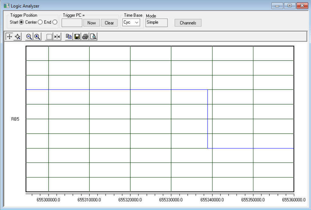
MPLAB software simulations for minimum frequency signal.
Output waveform with 50% duty cycle
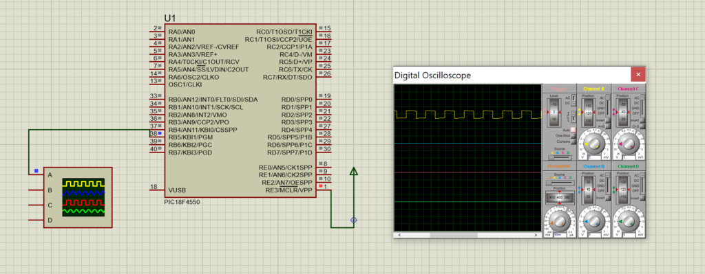
Simulation on Proteus for 50% duty cycle
Also read here