Design an Arduino based gas leakage detector
Design an Arduino based gas leakage detector. Human play a vital role in daily environment. Without human being the environment remains nothing. In other words man is the hero of this world, So environment provides more opportunities to human life and their health. Atmosphere is covered by a lot of gases and these gases play important role in our lives. Oxygen gas is used for respiration and it helps in burning process, while carbon dioxide is used for plants but besides this, Leakage of certain gases effects our lives and almost human losses occur. So up to some extent human life is badly affected by some sort of gases such as Carbon monoxide (CO), Carbon dioxide (CO2), liquefied petroleum gas (LPG) etc. Carbon monoxide is more hazardous to our lives. It is often called silent killer. The inhalation of this gas up to certain amount causes death. Likewise carbon dioxide is also a very dangerous gas.
But here our project is on natural gas leakage detection which is used in our home for domestic purpose. So we think to make a project called gas leakage detector which senses gas leakage and gives signal to the Arduino and further it is displayed on LCD (liquid crystal display) for viewing. Arduino is an open-source platform used for building and making electronics projects. Arduino consists of both a physical programmable circuit board (often referred to as a microcontroller) and a piece of software, or IDE (Integrated Development Environment) that runs on your computer, used to write and upload computer code to the physical board. Design an Arduino based gas leakage detector.
Problem Statement:
Domestically we use natural gas and it is very useful for burning purposes. If this gas is leaked in our kitchens, offices or factories and not sensed in time, it may lead to a fatal disaster, and may cause human loss. For this purpose we came forward with an idea of making such an electronic device to sense that leakage and alarm the respective persons to solve that leakage problem and save assets and human lives. It also down our economical rate.
Motivation:
To make our environment clean and away from all kind of dangerous gases we must take some steps like we would like to create a project which leads to detection of gases. So we design gas leakage detector to reduce the problem up to some extent. Gas leakage detection will not only provide us the significance in health department but also it will lead to raise our economy because when gas gets leaked it not only contaminates the atmosphere but also wastage of gases will down our economy.
Objectives:
The objectives of our project are as follows:
- To analyze the sensor for natural gas leakage detection.
- To design automatic Arduino based device for natural gas leakage detection.
- The device will show an alert message on LCD display along with buzzer activation.
Literature Review:
Carbon Monoxide (CO) poisoning is a seamless and dangerous problem in steel mill’s hot-process areas where the dirty and hazardous environment offers unique challenges to any deployed gas detection system. Slow accumulation of the gas causes headaches, dizziness, nausea and confusion which are harmful for workers’ safety and environmental protection.
The gas detection solution needs to be wireless and instantly deployable, as the steel mill could not afford the down time to install shielded cables. CO poisoning prevention system based on a Wireless Sensor Network (WSN) which continuously detects the CO level in a restrained space like in steel mills and upon alarming conditions, automatically activates countermeasure system to lower the CO concentration level.
Implementation of a WSN monitoring system connected to a customized actuator circuit which can switch the exhaust and alarm systems on and off autonomously. Air quality monitoring in indoor environments is of great significance for comfort and health, especially nowadays that people spend more than 80% of the day indoor.
It is important for ambient intelligent systems to be unobtrusive and to optimize the power consumption of the platforms in order to be able to live on batteries for several years. We present a system with aggressive energy management that involves three levels: sensor level, node level and network level. The sensor board we designed is a wireless sensor network (WSN) node, It contains two modalities – a gas sensor and a Pyroelectric InfraRed (PIR) sensor. The network is multimodal: it uses information from the PIR sensor and neighbor nodes to detect the presence of people and to modulate the duty cycle of the node and the Metal Oxide Semiconductor (MOX) gas sensor.
In this way we reduce the nodes’ activity and energy requirements, providing a reliable service at the same time. We simulate the benefits of the context-aware adaptive duty-cycling of the gas sensor activity and we demonstrate a significant lifetime extension compared to the continuously driven gas sensor. The project enables the users to monitoring different gases by using wireless sensor network and also ensures their management .
Safety plays a major role in today’s world and it is necessary that good safety systems are to be implemented in places of education and work. This work modifies the existing safety model installed in industries and this system also be used in homes and offices. The main objective of the work is designing microcontroller based toxic gas detecting and alerting system.
The hazardous gases like LPG and propane were sensed and displayed each and every second in the LCD display. If these gases exceed the normal level then an alarm is generated immediately and also an alert message (SMS) is sent to the authorized person through the (GSM). The advantage of this automated detection and alerting system over the manual method is that it offers quick response time and accurate detection of an emergency and in turn leading faster diffusion of the critical situation .
Design / Analysis:
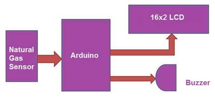
First the sensor will sense the leakage on the basis of gas density which is then sent to the Arduino in the form of electrical signal and further through programming/coding fed in Arduino, a signal will be sent to the peripheral components and a specific message will be displayed on LCD Display and also a buzzer will be activated . The whole phenomenon can be easily understood by observing Figure 1.
Components Used
- Arduino Pro Mini
- LPG Gas sensor Module
- Buzzer
- BC 547 Transistor
- 16×2 LCD
- 1K resistor
- Bread board
- 9 volt battery
- Connecting wires
LPG gas sensor module’s DO pin is directly connected to pin 18 (A4) of Arduino and Vcc and GND are connected to Vcc and GND of arduino. LPG gas sensor module consist a MQ3 sensor which detects LPG gas. This MQ3 sensor has a heater inside which needs some heater supply to heat up and it may takes up to 15 minute to get ready for detecting LPG gas. And a comparator circuit is used for converting Analog output of MQ3 in digital. A 16×2 LCD is connected with arduino in 4-bit mode. Control pin RS, RW and En are directly connected to arduino pin 2, GND and 3. And data pin D0-D7 are connected to 4, 5, 6, 7 of arduino. A buzzer is connected with arduino pin number 13 through a NPN BC547 transistor having a 1 k resistor at its base.
HOW THE PROJECT WORKS
The project operates in the following phases -:
1) Setting the sensitivity level – When the transmitter device is switched ON, the Arduino board loads the imported libraries and initializes LCD display. Some initial messages are displayed on the LCD and after 3 seconds the user is prompted to set the sensitivity level. The user can increase the sensitivity level in increments of 200, 250, 300, 350, 400, 450 and 500 by pressing one switch. On pressing the switch the value for reference increases then decreases repeatedly. Each value corresponds to concentration level in PPM. On pressing other switch, the sensitivity value is set for the reference.
2) Monitoring Gas Concentration – Once the reference value is set, the program code on Arduino keeps track of the analog value read from the MQ6 sensor. The device is programmed to read current sensor reading as analog value and convert it to a digital form. The digital measure is compared with the user defined reference value in an infinite loop.
3) Sending Danger Alert – If the current value measured from the sensor equals or exceeds the user defined reference value, the transmitter device is programmed to set the pin 6 of Arduino board HIGH. The pin 6 of the Arduino is connected to D0 bit of the encoder IC. Therefore, the RF transmitter starts transmitting the 0x1 as the data bit. The same bit is decoded as HIGH logic at the D0 bit of the decoder IC. When a HIGH bit is received at D0 bit, the buzzer circuit get the required supply and starts blowing. It should be taken care that in every receiver alarm circuit of the project, all the address bytes should be same as the address byte of the transmitter circuit and the buzzer section in the respective receiver circuit(s) should be connected at the D0 pins of the respective decoder ICs.
PROGRAMMING GUIDE
The receiver circuits will not have any programmable controller or IC. The receiver circuits should have the same address byte of the RF receiver configured, as of the transmitter RF module and buzzer sections should be connected to the D0 bits of decoder ICs. The transmitter circuit will have the program code for reading and comparing sensor value and sending RF data to the receiver sections.
First the LCD.h library needs to be imported and an object of LCD class needs to be initialized. An array to contain the predefined reference values also needs to be declared.
code for project of gas detector
#include <LiquidCrystal.h>//import the LCD library
LiquidCrystal lcd(13, 12, 5, 4, 3, 2); // Sensor sensitivity value set
int Ref[8] = { 0,200,250,300,350,400,450,500};
There needs to define two variables and assign them to the pins where tactile switches are connected. A variable is defined and assigned to the pin connected to D0 bit of encoder IC. Variables to store the reference sensor value and current sensor value are declared. A counter is also initialized.
// the setup routine runs once when you press reset:
int KEY1=A5; // RIGHT KEY
int KEY2=A4; //LEFT KEY
int buzzer=6; // For buzzer
int Setref=0; // user set sensor value
int count=0; //to count the number of times key pressed
int sensorValue=0; //for current sensor value
A setup() function is declared in which the baud rate for serial transmission of data to the LCD is set to 9600 bits per second using Serial.begin() function. The pins where tactile switches are connected are set to digital input and pin that has to relay logic to D0 pin of the encoder IC is set to the digital output using PinMode() function. The LCD is initialized using lcd.begin() function and initial messages are printed on it.
void setup() {
// initialize serial communication at 9600 bits per second:
Serial.begin(9600);
pinMode(KEY1, INPUT);
pinMode(KEY2, INPUT);
pinMode(buzzer, OUTPUT);
lcd.begin(16,2);
lcd.setCursor(0,0);
lcd.print(“Engineers Garage”);
lcd.setCursor(0,1);
lcd.print(” MQ6 Gas Sensor “);
delay(3000);
lcd.setCursor(0,1);
lcd.print(” “);
}
A loop() function is called in which first the messages are displayed on LCD to prompt the user to set a reference value of sensitivity. The status of both the switches is tracked by checking LOW logic at the respective pins and accordingly a value is stored in the variable holding reference value and the user actions are visually guided on the LCD display.
// the loop routine runs over and over again forever:
void loop() {
// read the input on analog pin 0:
lcd.setCursor(0,0);
lcd.print(“Press Left Bttn “);
lcd.setCursor(0,1);
lcd.print(“Set Sensitive”);
digitalWrite(buzzer,LOW);
if(digitalRead(KEY2) == 0)
{
count++;
Setref=Ref[count];
lcd.setCursor(13,1);
lcd.print(Setref);
if(count==8)
{count=0;}
delay(200);
}
if((digitalRead(KEY1) == 0) && count > 0)
{
lcd.setCursor(0,0);
lcd.print(“Sensitivity =”);
lcd.setCursor(13,0);
lcd.print(Setref);
lcd.setCursor(0,1);
lcd.print(“MQ6 sensor “);
An infinite while loop is called in which the current sensor value is read using the analogread() function at the A0 pin of the Arduino. The current sensor value is displayed on the LCD. The current value is compared with the reference value set by the user and if it equals to the reference value, the message “Alert !” is displayed on the LCD and the data bit D0 is set HIGH and LOW for five times repeatedly to blow the buzzer at the receiver circuit(s). The counter controlling HIGH and LOW logic transfer to D0 bit of RF data is initialized to zero in the end of the loop.
while(1)
{
sensorValue = analogRead(A0);
lcd.setCursor(11,1);
lcd.print(sensorValue );
delay(1); // delay in between reads for stability
if(Setref==sensorValue)
{
lcd.setCursor(0,0);
lcd.print(“Alert!! “);
lcd.setCursor(0,1);
lcd.print(“Alert!! “);
for(int i=0;i<=5;i++)
{
digitalWrite(buzzer,HIGH);
delay(500);
digitalWrite(buzzer,LOW);
delay(500);
}
delay(3000);
count=0;
break;
}
}
}
}
This completes the program code for Arduino Based Gas Leakage Detection Project using MQ5 Gas Sensor.
Also read here for more projects