Abstract
In this project we have described in detail about Arduino Project: Send Command with Serial Communication. After Implementing this project you will be able to use serial communication. In this project we have shown that how we can send commands to Arduino using serial communication. By the commands we mean, you will be able to turn ON individual LED, also you can turn ON all the lights or switch off them at a time. This project is showing how you can send commands to your Arduino.
Introduction
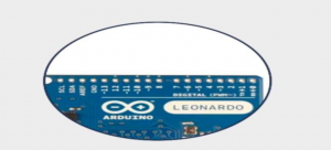
Serial Communication provides a simple and flexible way for your Arduino board to interact with your computer and other devices. This explains how to use this feature to send information to your computer using Arduino, Arduino UNO is an open-source, inexpensive, flexible, and easy-to-use programmable microcontroller board that can be integrated into a wide variety of electronic projects. This board can be connected to other Arduino boards, Arduino shields, Raspberry Pi boards and can control relays, LEDs, servos and motors as output. By the help of this we can turn on LEDs, fans or pumps.
Apparatus:
Arduino
Resisters
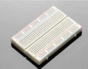
Breadboard
Connecting wires
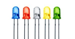
LEDs
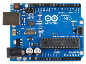
There are the following components of Arduino UNO board consists of:
Power Port
Microcontroller
Analog Input Pins
Digital pins
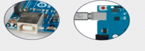
USB Connector
Reset switch
Crystal Oscillator
USB interface chip
TX RX LEDs
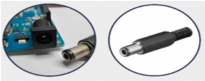
Power Port of Arduino
Arduino Board can be powered through a Ac to Dc adapter or a battery. The power source can be connected by plugging in a 2.1mm center positive plug into the jack of the board.
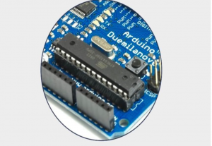
Microcontroller:
A microcontroller is an integrated circuit (IC) used to control other parts of an electronic system, usually through a microprocessor unit (MPU), memory, and some peripherals. These devices are optimized for embedded applications that require both processing functionality and agile, responsive interaction with digital, analog, or electromechanical components. At mega 328P is used on this board.
Analog Input Pins:
An Arduino chip’s analogue input pins are described (ATmega8, ATmega168, ATmega328P, or ATmega1280).
Converter (A/D)
The Arduino ATmega controllers have an internal 6 channel analog-to-digital (A/D) converter (8 channels on the Mini and Nano, 16 on the Mega). The converter returns numbers ranging from 0 to 1023 with a resolution of 10 bits. While most Arduino users utilize the analogue pins to read analogue sensors, the analogue pins also have all of the capability of general purpose input/output (GPIO) pins (the same as digital pins 0 – 13).
As a result, if a user requires more general-purpose input output pins but none of the analogue pins are in use, the analogue pins can be used for GPIO.
Pin placement
The aliases A0 (for analogue input 0), A1, and so on can be used in the same way as the digital pins. To set analogue pin 0 to an output and make it HIGH, for example, the code might look like this:
OUTPUT, pinMode(A0);
A0, HIGH); digitalWrite
Resistor pull-up
Pull-up resistors on the analogue pins work in the same way as pull-up resistors on the digital pins. They can be enabled by using a command like
pinMode(A0, INPUT PULLUP); / enable analogue pin 0 pull-up
Be aware however that turning on a pull-up will affect the values reported by analogRead().
Details and Caveats
The analogRead command will not work correctly if a pin has been previously set to an output, so if this is the case, set it back to an input before using analogRead. Similarly if the pin has been set to HIGH as an output, the pull-up resistor will be set, when switched back to an input.
The ATmega datasheet also cautions against switching analog pins in close temporal proximity to making A/D readings (analogRead) on other analog pins. This can cause electrical noise and introduce jitter in the analog system. It may be desirable, after manipulating analog pins (in digital mode), to add a short delay before using analogRead() to read other analog pins.
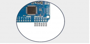
Digital pins:
These pins are labelled as Digital 0 to 13. This pins are used for output and input pins.
USB Connector:
USB port is used to load a program. It is also known as power port.
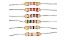
Resistor:
A passive two-terminal electrical component that implements electrical resistance as a circuit element is called resistors. In electronic circuits, resistors can be used to reduce current flow, adjust signal levels, to divide voltages, bias active elements, and terminate transmission lines, among other uses.
Breadboard
A thin plastic board used to hold electronic components (transistors, resistors, chips, etc.) that are wired together is called breadboard.It is used to develop prototypes of electronic circuits, breadboards can be used for future jobs. They can be used to create different kind systems but difficultly become commercial products
LEDs A semiconductor light source that emits light when current pass through it is called LEDs (light emitting diodes). In the semiconductor electrons combine with electron holes, releasing energy in the form of photons.
Procedure:
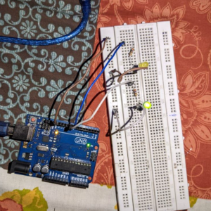
Take all the components.
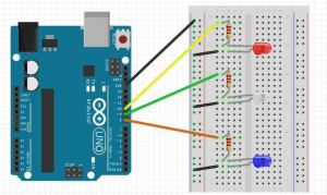
Then first insert the green light on the right side then yellow after him on the breadboard.
Attach the resistor with positive side of LED(green) and one side of the resistor attach with Arduino’s digital pin number 9, the negative pin of LED attach toh breadboard ground.
Then attach the resistor’s one side with positive side of LED and then attach to Arduino digital pin number 10, the negative pin of LED attach to the ground of breadboard.
And then attach the buses with each by connecting wires and the attach ground of breadboard with Ground of Arduino.
Now by USB connector connect Arduino with your computer.
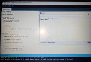
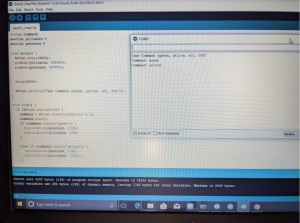
Then open the software on your computer and enter the desired code.
There is an arrow on the title bar press on it. TX and RX LEDs blinks of Arduino which means your code is being uploaded on the Arduino.
After entering command the LEDs blinks individually then both on and off at a time by entering the command in the command window.
Circuit Diagram:
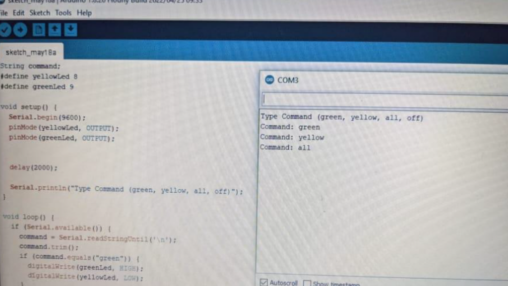
Code:
String command;
#define yelowLed 9
#define greenLed 10
void setup() {
Serial.begin(9600);
pinMode(yellowLed, OUTPUT);
pinMode(greenLed, OUTPUT);
delay(2000);
Serial.println(“Type Command (yellow, green, all, off)”);
}
void loop() {
if (Serial.available()) {
command = Serial.readStringUntil(‘\n’);
command.trim();
if (command.equals(“yellow”)) {
digitalWrite(yellowLed, HIGH);
digitalWrite(greenLed, LOW);
}
else if (command.equals(“green”)) {
digitalWrite(yellowLed, LOW);
digitalWrite(greenLed, HIGH);
}
else if (command.equals(“all”)) {
digitalWrite(yellowLed, HIGH);
digitalWrite(greenLed, HIGH);
}
else if (command.equals(“off”)) {
digitalWrite(yellowLed, LOW);
digitalWrite(greenLed, LOW);
}
else {
Serial.println(“bad command”);
}
Serial.print(“Command: “);
Serial.println(command);
}
Simulations and Results
Conclusion:
Sequential correspondence and investigating are vital for working with Arduino sheets. Basically, sequential correspondence is a technique that the board uses to speak with different gadgets – like another PC, a fringe, and so forth. At the point when we talk about Arduino sequential correspondence, it’s likewise important to recognize its actual parts (the Adriano’s sequential ports, for instance) and its product parts (involving the chronic screen in the Arduino IDE).
Also read here