Introduction
In this article we have described about Arduino Project: How to control the speed of DC motor? For numerous applications, speed control of direct current (DC) motors is critical. Setting a speed DC motor as the driving equipment, in particular, is required to be done remotely. Under those conditions, I did research on a DC motor speed control using the infrared remote control’s pulse width modulation (PWM) approach. PWM is a technique for controlling the speed of a DC motor. The data was sent to the ATmega16 microcontroller through the IR receiver using the TV remote control. This command is used to regulate the direction and speed of a DC motor using the L293D driver IC. A perforated disc connected to the motor shaft and placed between the photodiode as a sensor and the motor shaft is used to compute the speed of a DC motor.
A buck converter (step-down converter) is a DC-to-DC power converter that reduces voltage while increasing current from the input to the output (load). It’s a type of switched-mode power supply (SMPS) that has at least two semiconductors (a diode and a transistor, though modern buck converters frequently replace the diode with a second transistor for synchronous rectification) and at least one energy storage element, such as a capacitor, inductor, or both in combination. Filters built of capacitors (often in combination with inductors) are typically added to such a converter’s output (load-side filter) and input (input-side filter) to reduce voltage ripple (supply-side filter).
Components
- Arduino UNO
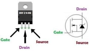
- MOSFET (IRF Z44N)
- Inductor(100mH)
- Capacitor (100µF)
- Diode
- Potentiometer
- Resistor (10k, 100ohm)
- DC motor
- Battery
Arduino UNO
It is a microcontroller board based on the ATmega328P. It has 14 digital input/output pins (of which 6 can be used as PWM outputs), 6 analog inputs, a USB connection, a power jack, an ICSP header and a reset button. It contains everything needed to support the microcontroller.

MOSFET: (Metal Oxide Semiconductor Field Effect Transistor) transistor is a semiconductor device that is widely used for switching purposes and for the amplification of electronic signals in electronic devices.
Working:
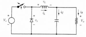
Along with the power electronics solid-state device that works as a switch for the circuit, another switch in the circuit is a freewheeling diode, as illustrated in the diagram below. To decrease current or voltage ripples, these two switches are connected to a low-pass LC filter. This aids in the production of controlled DC output. A pure resistor is linked across the entire arrangement and serves as the circuit’s load. The circuit operates in two modes.
- The first mode is when the power MOSFET, e., switch S1, is closed and thereby permits current to pass through it.
- When switch S2 is closed and S1 is opened, the second mode of operation
However, in order to show how automatically, the switch S2 will be closed. So, as we have discussed that the inductor in the circuit will store the energy so, once S1 will get open the inductor in the circuit will start acting as the source.
Circuit Diagram Of Buck Converter Using Arduino Nano
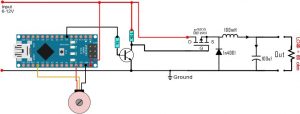
- A potentiometer is connected to the analogue input A0, as shown in the diagram
- Because the highest input voltage in this example is 12V, we will pick an output value between 1 and 12 volts with this
- Using the Arduino’s ADC, we’ll read a value between 0 and 1024, then map it to 1 to 244 in the code, which are the numbers utilized with the analogWrite()
- We’ll use this to apply a PWM signal to pin D3, with 1 being the lowest duty cycle and 244 being the highest.
- We add a little BJT driver using one S8050 NPN and two S8050 PNP transistors because the Arduino digital value is 5V.
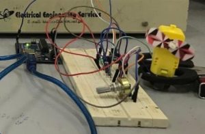
Implementation of the circuit:
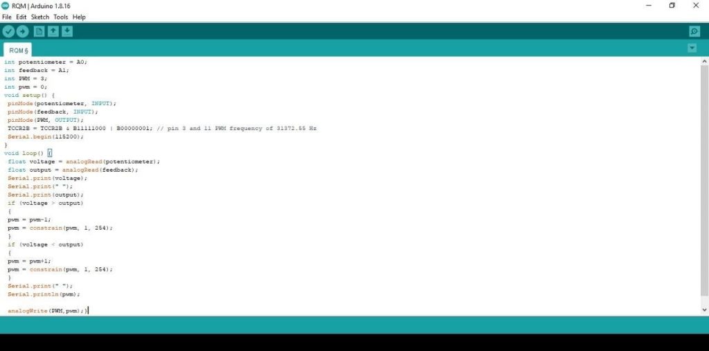
Arduino Code:
int potentiometer = A0; int feedback = A1;
int PWM = 3; int pwm = 0; void setup() {
pinMode(potentiometer, INPUT); pinMode(feedback, INPUT); pinMode(PWM, OUTPUT);
TCCR2B = TCCR2B & B11111000 | B00000001; // pin 3 and 11 PWM frequency of 31372.55 Hz
Serial.begin(115200);
}
void loop() {
float voltage = analogRead(potentiometer); float output = analogRead(feedback); Serial.print(voltage);
Serial.print(” “); Serial.print(output); if (voltage > output)
{
pwm = pwm-1;
pwm = constrain(pwm, 1, 254);
}
if (voltage < output)
{
pwm = pwm+1;
pwm = constrain(pwm, 1, 254);
}
Serial.print(” “); Serial.println(pwm); analogWrite(PWM,pwm);
}
Conclusion:
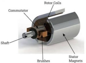
A shunt or separately excited dc motor has a torque-speed characteristic whose speed drops linearly with increasing load torque. Its speed can be controlled by changing its field current, its armature voltage or its armature resistance. We saw the working of DC motor using Arduino codes.
DC motor speed control with Arduino
Also check here