Table of Contents
How to interface DC motor with PIC microcontroller?
How to interface DC motor with PIC microcontroller? DC motors are electrical devices that run on DC electricity. DC converts electrical energy into mechanical energy. They are used in wide range of applications from toys to electric cars. By using the concept of interfacing of DC Motor with PIC, we will be able to control the direction and speed of the motor and on robotic applications.
Structure:
DC motor has a stator; which is a combination of stationary magnets and an armature; made up of an iron core which is completely wrapped in insulated wire. Amount of current which is sent to the coil depends upon the strength of magnetic field. As the amount of current in the coil increases the strength of magnetic field also increases. In order to improve the controls on the motor stator are used.
There are three types of electrical connections between the stator and the rotor: series, shunt, and compound connections. In series, an armature and field windings is connected with DC source in series connection. In parallel, field windings and an armature is connected with DC source in parallel connection. The composite ratio is used in applications that require high starting torque and good speed control. It includes shunt and serial field and armature connections, as the name implies.
DC Motor Interfacing with PIC Microcontroller:
The current that microcontroller provides is much less than the current DC motors required so a separate controller needs to be used. Different voltages are required for DC motors. If we want to use low voltage controller for operating high voltage motor then it will not possible.
The few considerations must be follow when the circuit is designing.
- The circuit will be able to handle a large amount of current; usually greater then 250mA.
- It should be able to filter back emf for coil safety.
To solve the back EMF problem, Power transistor will be used to handle a large amount of current and a diode on DC motor. The diode can prevent current from flowing in the opposite direction, effectively blocking back EMF.
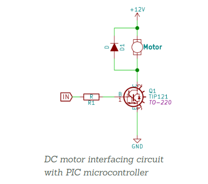
Since the motor voltage is 12V in this scenario, the control transistor will drive the motor with these requirements. Examples are TIP121 and D880. The motor will be driven in one direction and the speed will be varied using PWM by this circuit only.
Firmware:
The circuit is attached to the microcontroller’s RB0 pin. This pin output mode must be developed.
TRISBbits are a form of TRISBbits.
TRISB0 = 0; / Set RB0 to be the output.
Now, if we need to run the motor, switch it to HIGH mode.
PORTBbits.RB0 = 1; / Activate the motor
H bridge:
Four transistors make up a traditional H-bridge circuit. There are 2 PNPs located on top while other 2 NPNs are at bottom. The four input A,B,C and D are circuited by the driver. The terminal B is grounded and terminal C is pulled high when transistor Q2 and Q3 conducts. Current flows from Vcc through Q2, through the engine and finally to ground through Q3. The motor is activated in single direction.
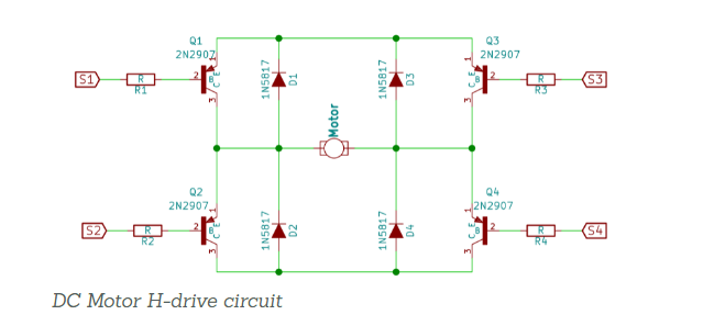
Current flows from left to right when D is grounded and A is Vcc and the transistors Q1 and Q4 turn on via motors. To transfer current from right to left B should be grounded and terminal C should be in Vcc. In opposite direction, the motor will rotate.
Driver ICs:
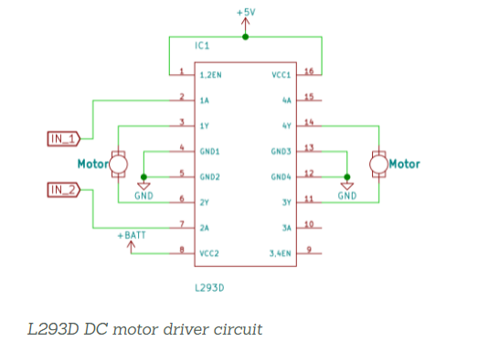
Any current driver with an appropriate current output and the variety of motor driver chips available can be used. However, we’ll need an H-bridge driver IC like the L293D to use it in both directions. This integrated circuit will rotate in either direction. A circuit using the L293D is shown below.
Workig Algorithm:
Forward:
1 or 3 Pin has high Input; In1 = 1, In3=1
2 or 4 pin has Low Input; In2 = 0 , In4 = 0
EN has High Pin; En1 = 1 , En2 = 1
Reverse:
EN Pin High; En1 = 1 , En2 = 1
1 or 3 pin has Low Input; In1 = 0 , In3 = 0
2 or 4 pin has Low Input; In2 = 1 , In4 = 1
Code :
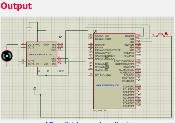
When we push the button, the motor in this code rotates forward. In this example, the button’s one end is connected to +5v. In the if function, we are testing with (sw==1)if 1. We should use (sw==0) if 0 and if end to field is bind.
#include<pic.h>
#define 1In RBO
#define 2In RB1
#define sw RB2
Void main()
{
TRISBO=O;
TRISB1=O;
TRISB2=0;
while(1) {
if(sw==1) {
1In=1;
2In=O;}
else
{
1In= 2In=O;}
}}
The maximum current capacity of L293 is 600mA per channel. As a result, don’t use a motor that uses more. The L293 has a supply voltage range of 4.5 to 36V DC. As a result, in that price range we can use a motor. DC gear motors are commonly used in robotic applications. As a result, the same principle is applied to the Gear motor.
Also read here
How temperature sensor is interfaced with PIC micro controller?