
Introduction:
How to Design RGB Mood Lamp using Arduino? In this project, we use LEDs of different colors to create any new color for lamp according our choice that’s the purpose of mood lamp project.
We use Arduino software for code compilation and then for uploading it to the Arduino UNO for powering it up and for hardware output. Resistors with each of the led are used to control and restrict the current.
The basic purpose of RGB mood lamp project is to generate a lamp with our favorite color combination.
What is mood lamp?
Mood lamps are lighting devices that are used to establish a particular feeling or mood within a room. In some cases, this type of lamp may be a small device that is plugged into an outlet and creates points of light near the floor line of the room. Other examples of a mood lamp may be used to illuminate specific points along the walls or cast a soft light over a larger piece of furniture in the room.
Components:
- Arduino
- LEDs
- Red
- Green
- Yellow
- Resistors
- Jumper Wires
Working:
We used RGB LED. This is one 5mm LED, with four legs (some have more). One leg is a normal (positive) or normal cathode (negative) and the other three go to the opposite terminal of the red, green, and blue LEDs inside the lamp.
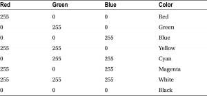
The RGB value of 255, 0, 0 can give us pure red. The value of 0, 255, 0 will give pure green, and 0, 0, 255, pure blue. By mixing these, we can get any color we like. This is an additional color model. In this case, we set the RGB values to a random number set (256), which will give us a number between 0 and 255 combined (as the number will always be from zero upwards). If you transfer one number to a random function (), you will return the value between 0 and 1 under the number; random (1000) will return a number between 0 and 999.
If you give two numbers as parameters, it will replace the random number between the integer plus the minus 1 (−1). For example, random (10,100) will return a random number between 10 and 99. In the main program loop, we first look at the initial and end RGB values and then determine what value is needed to develop a single value. in another in 256 steps (as PWM value can be between 0 and 255 only)
Circuit Diagram of RGB Mood Lamp

Code for RGB Mood Lamp Circuit
float RGB1[3];
float RGB2[3];
float INC[3];
int red, green, blue;
int RedPin = 11;
int GreenPin = 10;
int BluePin = 9;
void setup()
{
Serial.begin(9600);
randomSeed(analogRead(0));
RGB1[0] = 0;
RGB1[1] = 0;
RGB1[2] = 0;
RGB2[0] = random(256);
RGB2[1] = random(256);
RGB2[2] = random(256);
}
void loop()
{
randomSeed(analogRead(0));
for (int x=0; x<3; x++) {
INC[x] = (RGB1[x] – RGB2[x]) / 256; }
for (int x=0; x<256; x++) {
red = int(RGB1[0]);
green = int(RGB1[1]);
blue = int(RGB1[2]);
analogWrite (RedPin, red);
analogWrite (GreenPin, green);
analogWrite (BluePin, blue);
delay(100);
RGB1[0] -= INC[0];
RGB1[1] -= INC[1];
RGB1[2] -= INC[2];
}
for (int x=0; x<3; x++) {
RGB2[x] = random(556)-300;
RGB2[x] = constrain(RGB2[x], 0, 255);
delay(1000);
}
}
Code Explanation:
The RandomSeed command is used to create random numbers (actually fake-random). Computer chips cannot generate truly random numbers, so they use a mathematical function that produces the longest random sequence of random numbers before duplication.
By setting “seeds,” you can tell the computer when the sequence has started to recover random numbers. In this case, the value we give to randomSeed is the value learned from the analog PIN 0.Since we do not have an object connected to the analog PIN 0, we will only read a random number created by the analog sound. Once we have set a “seed” for our random number, we can create one using random function ().We then had two sets of RGB values stored in a three-item list. RGB1 is the RGB value we want the lamp to start with (in this case, all zero or off).
Simulation Results:
We used Arduino to design a mood lamp, a code is constructed. Mood lighting differ somewhat from other lamps in that their purpose is not so much practical as aesthetic. Reading lamps for example tend to provide bright light to a given space in order to make it possible to read a book or magazine without creating strain on the eyes. The code constructed allows Smooth RGB mood lamp working. It changes an RGB LED’s color smoothly that only turns on
when it’s dark around it. The brightness of the LEDs follows the equations LDR in Analog Input 0 to read the ambient light, variable are to store the value of the ambient light , red LED in Digital Pin 11 (PWM),green LED in Digital Pin 10 (PWM) and blue LED in Digital Pin 9 (PWM)It tell arduino it’s an output by setting all the outputs to low. We can calculate the brightness for the red LED, the green LED and calculate the brightness for the blue LED. it store the ambient light and starts only if the ambient light is very low by write the brightness on the LEDs.
Conclusion:
In this experiment we designed a mood lamp using RGB LEDs. Overhead lighting is used when there is a need to illuminate the majority of the space, such as in a classroom or laboratory. By contrast, a mood lamp is used to help create a specific ambiance within the room as a means of making the space more attractive and welcoming in some manner.
Video demonstration for Project RGB Mood Lamp Using Arduino
https://www.youtube.com/watch?v=hdaYZc2C36Q
Also click below for more projects
- Arduino Project: How to control the speed of DC motor?
- Arduino Project: Send Command with Serial Communication
- Arduino Project: LED Fire Effect
- How to select an Arduino?
- How Raspberry Pi Is Better than Arduino For Learning Electronics?
- How to design an LED Flasher on Arduino Board
- Design an Arduino based gas leakage detector
- Design of Traffic Light Control system using Arduino