Voltage Multipliers
In this article you will learn about what are the Voltage Multipliers? Voltage multipliers are the circuits that we use for increasing the peak rectified voltages without increasing the transformer ratings or disturbing the turn ratio. The clamping action is used for increasing the magnitude which is implemented using the capacitors. Usually factors of multiplication of 2, 3, and 4 are common. Voltage multipliers are used for high voltages and low current applications such as CRT (Cathode Ray Tubes) and particle accelerators.
Basically diodes and capacitors can be connected in various configurations to produce the filtered, rectified voltages that are integer multiples of peak value of an input sine wave. One advantage of voltage multiplier is that high voltages can be obtained without using the high voltage transformer.
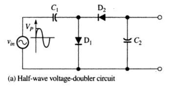
Half-Wave Voltage Doubler
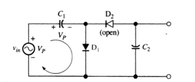
The following figure shows the circuit of voltage doubler which uses 2 capacitors and two diodes. When the input voltage goes to the positive peak Vp, the diode D1 is forward biased. Because the forward resistance of diode D1 is very small, the capacitor charges to Vp-0.7V (practically) or Vp (ideally) as shown in Fig 2. The current takes the whole conduction path via diode D1 and does not go to the branch where D2 is present.
During the negative half cycle of input voltages, Diode D1 is reverse biased because of the polarity of the voltages across the capacitor C1. Now, diode D2 is forward biased and it will charge the capacitor C2. Since the capacitor C1 can not discharge, the peak voltages on C1 adds to the secondary voltages to charge the capacitor C2 up to the 2Vp. The voltages across the capacitor C2 can be found using the KVL (Kirchhoff’s Voltage Law).
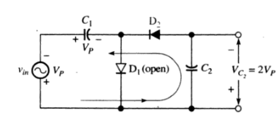
VP+VC1-VC2=0
Since VC1= VP
So , VC2=2 VP
During the next positive half cycle of input voltages, D2 is again reverse biased and the voltages at the output remains equal to VC2=2 VP. You must always note the polarity of output voltages carefully. If a load is connected across the capacitor C2, then C2 will discharge via load during the positive half cycle when D2 will be reverse biased. It will recharge to 2 VP during next negative half cycle. The PIV (peak inverse voltages) of each diode must be 2 VP. If we reverse the direction of diodes, then the output voltages will have opposite polarity.
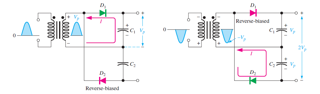
Full-Wave Voltage Doubler
A full-wave voltage doubler is shown in the figure below. During the positive half cylce of input voltages, diode D1 is forward biased and capacitor C1 charges to the peak value of input voltages. During the negative half cycle, diode D2 is forward biased and C2 charges to the Vp. Since both capacitors are connected in series, so the voltages will be added for getting the resultant output voltages as depicted in the following diagram. The difference between half wave voltage doubler and full wave voltage doubler is that the effective capacitance is in series in case of full wave voltage doubler which is less than the individual capacitance of C1 and C2. The lower capacitance will provide the poorer filtering action than the single capacitor circuit,
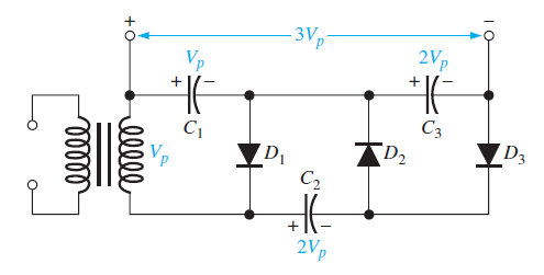
Voltage Tripler
The addition od another capacitor-diode pair will add another vp into voltage doubler circuit. A voltage tripler circuits is shown in the figure below. During the positive half cycle of input voltages, D1 is forward biased and C1 charges to Vp. When the negative half cycle of input voltages arrives, D2 is forward biased and C2 charges to 2Vp. During the next positive half cycle of input D3 is forward biased and C3 charges to 2 VP since theC1 voltages are added into input voltages for charging the capacitor C3. The output is taken across C1 and C3 as shown in the following figure.
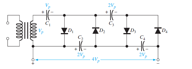
Voltage Quadrupler
The voltage quadrupler circuit is shown in the figure below. A voltage quadrupler circuit is an electrical circuit that has the capability to generate an output voltage that is approximately four times the peak input voltage. It is a type of voltage multiplier circuit that utilizes a combination of diodes and capacitors to achieve this voltage multiplication effect.
The basic operation of a voltage quadrupler circuit involves the alternating charging and discharging of capacitors in a specific configuration. The circuit typically consists of four diodes, four capacitors, and a load resistor. The diodes are arranged in a bridge configuration, forming a rectifier that allows current to flow in only one direction.
During the positive half-cycle of the input voltage, two of the diodes conduct, allowing the capacitors to charge to the peak input voltage. In this charging phase, the capacitors accumulate charge, storing electrical energy. During the negative half-cycle of the input voltage, the other two diodes conduct, effectively flipping the orientation of the capacitors in the circuit.
In the discharging phase, the charged capacitors are connected in series, resulting in the summation of the voltage across them. This series-connected arrangement effectively multiplies the voltage by a factor of two. By connecting an additional capacitor in parallel to the series-connected capacitors and repeating this process, the output voltage can be further doubled.
The voltage quadrupler circuit achieves its multiplication effect by capitalizing on the charging and discharging characteristics of the capacitors. Each charging phase accumulates energy, and the subsequent discharging phase doubles the voltage, resulting in an output voltage that is four times the peak input voltage.
It is worth noting that the actual output voltage of a voltage quadrupler circuit may vary from the theoretical value due to losses, component tolerances, and other factors. Practical considerations, such as the selection of appropriate diodes and capacitors with suitable voltage and current ratings, are crucial for the reliable and efficient operation of the circuit.
Voltage quadrupler circuits find applications in various domains, including power supplies, signal processing, and high-voltage systems. Their ability to generate higher voltages from lower input voltages makes them useful in situations where increased voltage levels are required, while minimizing the need for more complex and expensive voltage conversion techniques.
Also read here