Series and Parallel Circuits
Series and parallel circuits are fundamental building blocks in the field of electrical engineering and electronics. Understanding the characteristics, behavior, and applications of these circuit configurations is essential for designing, analyzing, and troubleshooting electrical systems of varying complexities.
This comprehensive guide explores the principles, properties, and practical implications of series and parallel circuits, covering topics ranging from basic concepts to advanced applications and real-world examples.
Part 1—Fundamentals of Series Circuits
1. Definition and Characteristics:
Introduction to series circuits, where components are connected end-to-end along a single path. Exploring the key characteristics of series circuits, including constant current flow, voltage division, and cumulative resistance.
2. Ohm’s Law in Series Circuits:
Applying Ohm’s Law to analyze voltage, current, and resistance in series circuits, including calculations for total resistance, individual voltage drops, and power dissipation.
3. Series Circuit Analysis:
Techniques for analyzing series circuits using Kirchhoff’s voltage law (KVL) and basic circuit laws, including nodal analysis and mesh analysis. Practical examples and step-by-step problem-solving strategies.
4. Applications of Series Circuits:
Real-world applications of series circuits in electronics, electrical appliances, and industrial systems. Examples include Christmas lights, LED arrays, voltage dividers, and temperature sensors.
Example of Series Circuit
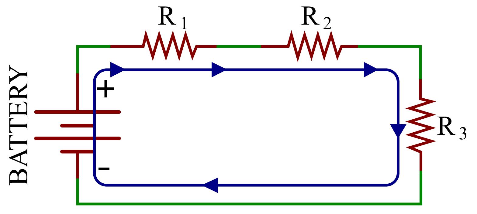
A series circuit is formed when electrical components are connected one after another, providing only one path for current to flow.
Characteristics:
-
The same current flows through all components.
-
The supply voltage is divided across the components.
-
The total resistance is equal to the sum of individual resistances.
-
If one component fails or becomes disconnected, the entire circuit stops working.
\[
\text{Given:}
\]
\[
R_1=2\,\Omega,\quad R_2=4\,\Omega,\quad
R_3=6\,\Omega,\quad V=12\,V
\]
\textbf{Step 1: Calculate Total Resistance}
\[
R_T=R_1+R_2+R_3
\]
\[
R_T=2+4+6=\boxed{12\,\Omega}
\]
\textbf{Step 2: Calculate Circuit Current}
\[
I=\frac{V}{R_T}
\]
\[
I=\frac{12}{12}=\boxed{1\,A}
\]
\textbf{Step 3: Calculate Voltage Across Each Resistor}
\[
V_1=IR_1=1\times2=\boxed{2\,V}
\]
\[
V_2=IR_2=1\times4=\boxed{4\,V}
\]
\[
V_3=IR_3=1\times6=\boxed{6\,V}
\]
\textbf{Step 4: Verify Using KVL}
\[
V=V_1+V_2+V_3
\]
\[
12=2+4+6=\boxed{12\,V}
\]
Part 2: Fundamentals of Parallel Circuits
1. Definition and Characteristics:
Introduction to parallel circuits, where components are connected across multiple paths, allowing independent current flow through each branch. Exploring the key characteristics of parallel circuits, including constant voltage across branches and reciprocal resistance.
2. Ohm’s Law in Parallel Circuits:
Applying Ohm’s Law to analyze voltage, current, and resistance in parallel circuits, including calculations for total conductance, individual branch currents, and power distribution.
3. Parallel Circuit Analysis:
Techniques for analyzing parallel circuits using Kirchhoff’s current law (KCL) and basic circuit laws, including loop analysis and superposition. Practical examples and troubleshooting strategies for complex parallel circuits.
4. Applications of Parallel Circuits:
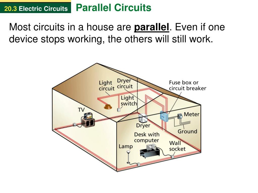
Real-world applications of parallel circuits in electrical wiring, power distribution, and circuit protection. Examples include household wiring, automotive electrical systems, and battery packs.
Example of parallel circuits
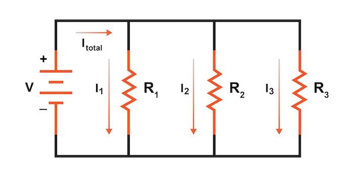
A parallel circuit is formed when electrical components are connected across the same two nodes, providing multiple paths for current to flow.
Characteristics:
-
The voltage across every parallel branch is the same.
-
Current is divided among different branches.
-
Total current is equal to the sum of branch currents.
-
If one branch becomes disconnected, the other branches can continue operating.
-
Total resistance is always less than the smallest individual branch resistance (for positive resistances).
\[
\text{Given:}
\]
\[
R_1=2\,\Omega,\quad R_2=4\,\Omega,\quad
R_3=6\,\Omega,\quad V=12\,V
\]
\textbf{Step 1: Calculate Equivalent Resistance}
\[
\frac{1}{R_T}=
\frac{1}{R_1}+\frac{1}{R_2}+\frac{1}{R_3}
\]
\[
\frac{1}{R_T}=
\frac{1}{2}+\frac{1}{4}+\frac{1}{6}
\]
\[
\frac{1}{R_T}=\frac{6+3+2}{12}
=\frac{11}{12}
\]
\[
R_T=\boxed{\frac{12}{11}=1.09\,\Omega}
\]
\textbf{Step 2: Calculate Total Current}
\[
I_T=\frac{V}{R_T}
\]
\[
I_T=\frac{12}{12/11}=\boxed{11\,A}
\]
\textbf{Step 3: Calculate Current Through Each Branch}
\[
I_1=\frac{V}{R_1}=\frac{12}{2}
=\boxed{6\,A}
\]
\[
I_2=\frac{V}{R_2}=\frac{12}{4}
=\boxed{3\,A}
\]
\[
I_3=\frac{V}{R_3}=\frac{12}{6}
=\boxed{2\,A}
\]
\textbf{Step 4: Verify Using KCL}
\[
I_T=I_1+I_2+I_3
\]
\[
11=6+3+2=\boxed{11\,A}
\]
Part 3: Combination Circuits and Circuit Analysis Techniques
1. Series-Parallel Circuits:
Analyzing circuits that contain both series and parallel elements, known as combination circuits. Strategies for simplifying complex circuits using equivalent resistance and voltage divider rules.
2. Thevenin’s and Norton’s Theorems:
Introduction to network theorems for simplifying and analyzing complex circuits. Exploring Thevenin’s theorem and Norton’s theorem, along with practical applications and limitations.
3. Mesh and Nodal Analysis:
Advanced circuit analysis techniques for solving complex circuits with multiple loops and nodes. Step-by-step procedures for applying mesh analysis and nodal analysis to circuit problems.
4. Transient Analysis:
Introduction to transient analysis in circuits, including the response of series and parallel circuits to sudden changes in voltage or current. Analyzing transient behavior using differential equations and circuit simulation software.
Part 4: Practical Considerations and Applications
1. Circuit Design and Optimization:
Strategies for designing and optimizing series and parallel circuits for specific applications, including component selection, voltage/current requirements, and power dissipation considerations.
2. Troubleshooting Techniques:
Common troubleshooting techniques for diagnosing and resolving issues in series and parallel circuits, including open circuits, short circuits, and voltage/current abnormalities.
3. Safety and Standards:
Safety considerations and standards for working with series and parallel circuits, including electrical code compliance, insulation requirements, and protective measures for preventing electrical hazards.
4. Emerging Technologies and Innovations:
Emerging trends and innovations in series and parallel circuit design, including flexible electronics, printed circuit boards (PCBs), and integrated circuit (IC) packaging techniques.
Series and parallel circuits are fundamental concepts in electrical engineering, providing the foundation for understanding, designing, and analyzing complex electrical systems. By mastering the principles and techniques outlined in this comprehensive guide, engineers, technicians, and enthusiasts can confidently navigate the intricacies of series and parallel circuits, unlocking endless possibilities for innovation and advancement in the field of electronics and beyond. Whether you are a student learning the basics or a seasoned professional exploring cutting-edge technologies, this guide offers valuable insights and resources for harnessing the power of series and parallel circuits to drive progress and innovation in the modern world.
Part 5: Advanced Applications and Special Circuits
1. Impedance Matching:
Understanding impedance matching techniques in series and parallel circuits to optimize power transfer between components, such as antennas, amplifiers, and transducers. Exploring the Smith chart and transmission line theory for impedance matching design.
2. Filters and Frequency Response:
Analysis and design of passive and active filters using series and parallel circuit configurations. Exploring low-pass, high-pass, band-pass, and band-stop filter topologies, along with frequency response characteristics and applications.
3. Resonant Circuits:
Investigation of resonance phenomena in series and parallel circuits, including RLC (resistor-inductor-capacitor) circuits and LC (inductor-capacitor) circuits. Understanding resonance frequency, bandwidth, and quality factor in resonant circuit design.
4. Switching Circuits and Logic Gates:
Introduction to digital electronics and logic circuits, including basic gates (AND, OR, NOT) implemented using series and parallel configurations of transistors. Exploring sequential logic circuits, flip-flops, and memory elements.
Part 6: Special Topics and Future Directions
1. Quantum Circuits:
Overview of quantum circuit design principles and applications, including quantum gates, qubits, and quantum algorithms. Exploring the potential of quantum computing to revolutionize information processing and cryptography.
2. Biomedical Circuits:
Introduction to biomedical circuit design for healthcare applications, such as medical devices, biosensors, and implantable electronics. Exploring series and parallel circuits in electrocardiography (ECG), electroencephalography (EEG), and medical imaging systems.
3. Flexible and Stretchable Circuits:
Emerging technologies for flexible and stretchable electronics, including series and parallel circuit configurations on flexible substrates. Applications in wearable devices, electronic skin, and conformal electronics for healthcare and robotics.
4. Energy Harvesting Circuits:
Design and optimization of series and parallel circuits for energy harvesting from ambient sources, such as solar, thermal, and vibrational energy. Applications in autonomous sensors, wireless sensor networks, and IoT (Internet of Things) devices.
Series and parallel circuits represent the backbone of electrical and electronic systems, enabling a wide range of applications across diverse industries and disciplines. From basic circuit analysis to advanced applications in quantum computing and biomedical engineering, the principles and techniques discussed in this comprehensive guide serve as invaluable tools for engineers, researchers, and innovators.
3. Comparison Between Series and Parallel Circuits
| Parameter | Series Circuit | Parallel Circuit |
|---|---|---|
| Current | Same throughout | Divides among branches |
| Voltage | Divided | Same across branches |
| Resistance | Adds directly | Reciprocal sum |
| Current paths | One | Multiple |
| Total resistance | Increases with added resistors | Decreases with added branches |
| Component failure | Entire circuit may stop | Other branches continue |
| Connection | End-to-end | Across common nodes |
Also read here
Ideal, Complete and practical Diode Models with Solved Examples