Introduction to clampers
What are the clampers circuits and how they work? There are many application in electronics where we need to restore the DC level of a particular signal. This can be done using the batteries, but using batteries have some drawbacks. The first drawback is the size of batteries. Batteries are bulky in sizes and also have large sizes as compared to the actual circuits where we need to restore the DC level. Second drawback is their maintenance. They need to be replaced after a specific period of time or need to be recharged if they are rechargeable. So using batteries is not a good idea to restore the DC level of a circuit. Here comes the clampers. Clampers are the DC level restorers that adds specific DC level to your circuit where needed. The plus point is they do not alter the shape of waveform of the actual signal. They will just shift “up” or “down” your waveform according to the requirement.
A clamper circuit consists of a diode, a resistor and a capacitor. The purpose of the diode is to provide switching. The capacitor sores the charges that is used to restore the DC level in the waveform. Resistor provides the leakage path. The capacitor and the resistor should be chosen so that the capacitor do not discharge while the diode is not conducting in the circuit. It means the best clamping action is performed when capacitor retains its voltages. This can be determined using the time constant T=RC. During the analysis we will assume that capacitor charges and discharges in time equal to 5T. If RC time constant is 100 times the time period of input signal then the excellent clamping action is performed.
How many types of clampers are there?
There are basically two types of clampers.
- Positive clampers
- Negative clampers
Positive Clampers
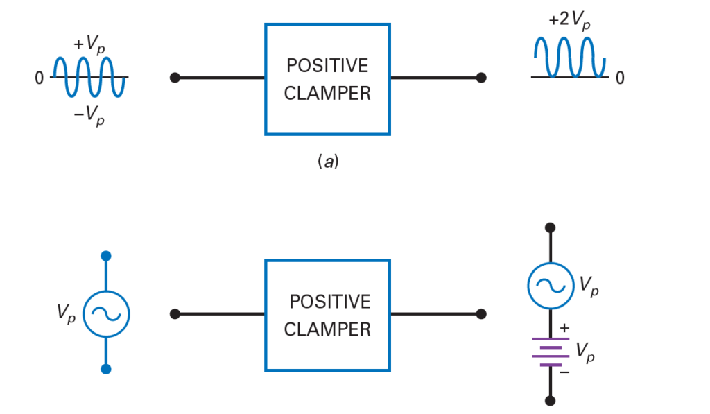
Positive clampers will shift your voltage waveform upward by adding the positive DC voltage level in it. It will shift the waveform such that the negative peak ideally will be at 0 V level. The above figure shows the equivalent circuit where both ac source and capacitor voltages acting as DC source are superimposed on each other.
The following figure shows a positive clamper circuit. The other hint of positive clamper is the direction of the diode. If the diode is pointing upward then it means these are the positive clampers and if the diode is pointing downward then that is the negative clamper circuit.
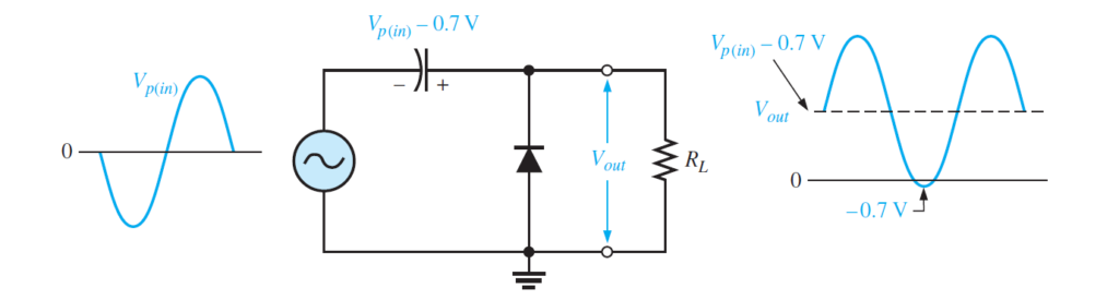
Working of the positive clamper circuit
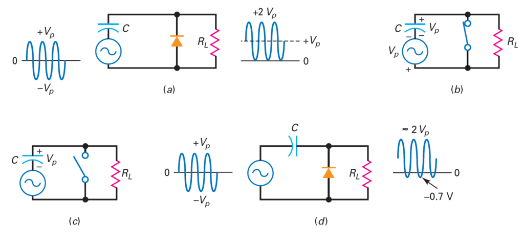
For understanding the working of any clamper circuit, we will start analysis of the circuit from that portion of the waveform at which diode is forward biased so capacitor can charge its voltages. In the above circuit, the analysis will begin at the negative peak of input wave form. When negative cycle arrives, then the capacitor will charge through diode upto VP-0.7V. When the positive cycle arrives the diode will not conduct, capacitor will retain its voltages and voltages across the load resistor will be 2VP-0.7V. The negative peak will be ideally at 0V while practically at -0.7 as shown in the above figure. The DC reference level is set by the capacitor voltages that are known as offset voltages and their value is equal to VP-0.7V.
Negative Clampers
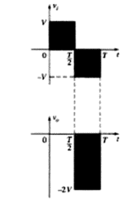
As the name indicates. negative clampers will shift the output waveform downward. It means the positive peak will be at 0.7V practically and at 0V ideally. While the negative peak will be at – 2VP+0.7V.
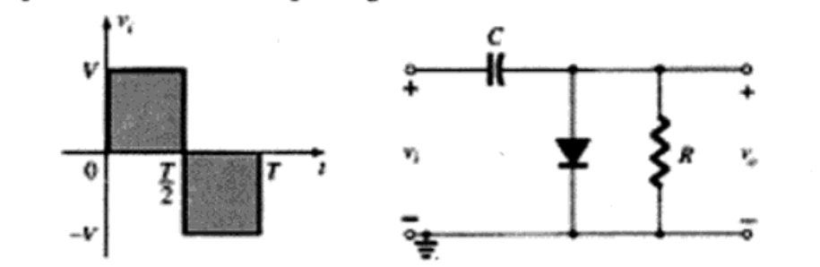
The negative clamper circuit has capacitor at the input side while resistor and diode are connected in parallel with output side. In the above figure, diode will be forward biased at the positive part of the input cycle. During this time capacitor will charge instantaneously. For the interval 0 to T/2 the circuit can be represented as
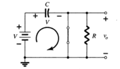
It can be seen that the diode is replaced by the short circuit or like a closed switch while capacitor charges through it. Lets say it reaches up to VP ideally. The polarity of the capacitor voltages is shown above. Now during the off period of the diode the capacitor retains its stored voltages. The diode acts as an open circuit and the path of the current is through capacitor and the load resistor. But as we have assumed that the capacitor does not discharge so these voltages will appear across the load resistor as
-V-V+0.7=-2Vp-0.7V.
Here the negative sign indicates that the waveform is shifted downward. It is to be noted that the total swing of output voltage is as that of input voltages. The output of the above circuit is shown below.
Also read here:
https://eevibes.com/how-tunnel-diode-works/