How to interface Stepper Motor with PIC ?
How to interface Stepper Motor with PIC ? First of all, here we discuss the stepper motor, PIC Micro-Controller and then their Interface with each other.
Stepper Motor
A stepper motor is a widely used device that translates electrical pulses into mechanical movement. In application such as disk drives, dot matrix printers, and robotics, the stepper motor is used for position control. Stepper motors commonly have a permanent magnet rotor(also called the shaft) surrounded by a stator. There are also stepper called variable reluctance stepper motor that do not have a permanent magnet rotor. The most common stepper motors have a four stator windings that are paired with a center-tapped common. This type of is commonly referred to as a four phase or unipolar stepper motor. Mainly two types of stepper motors are commonly used which is Unipolar and Bipolar. Unipolar is easier to operate, control and also easily available.
Stepper Motor is a very special kind of designed motor which rotates in steps. The speed of stepper motor depends upon the rate of electrical signals applied to it. Different patterns can control stepper motor’s direction and rotation type.
PIC Micro-Controller :
PIC stands for Peripheral Interface Controller. PIC Micro-Controller was designed by Microchip. This micro-controller is a very fast, simple and easily use for Implementation and performance. This micro-controller is easy to program and also it is easy to interface with other Peripherals like stepper motors.
PIC Families include PIC16, PIC17,PIC18,PIC24 and PIC32. Popular micro-controllers are Atmega 8,16,32, Arduino and Community.
Interfacing Stepper Motor with PIC
Here we are going to interface stepper motor with PIC by using 28BYJ-48 stepper motor and PIC 16f877a for this project and both are cheap and easily available.
28BYJ-48 Stepper Motor
It is 5V DC unipolar stepper motor. We also use a Module available with this motor which consist ULN2003 Stepper Motor Driver IC. It is a Darlington pair array, As PIC microcontroller couldn’t provide enough current to the drive, it is used to drive the motor. ULN2003A is capable to drive 500mA of load with 600mA of peak current.
How to Interface stepper motor
For Interfacing of stepper motor with PIC, we rotate stepper motor which can be done as by this process.
If we see the datasheet we will see that :
Inside the motor there are two center tapped coils available. Red Wire is the common for both which will be connected at VCC or 5V.
Other 4 wires pink , red , yellow and blue will control the rotation depending on the electrical signal which is given to it. Also, depending on the movement, this motor can be controlled using 3 steps. Full drive mode, Half Drive mode and Wave Drive mode.
Three Driving Modes of Stepper Motor
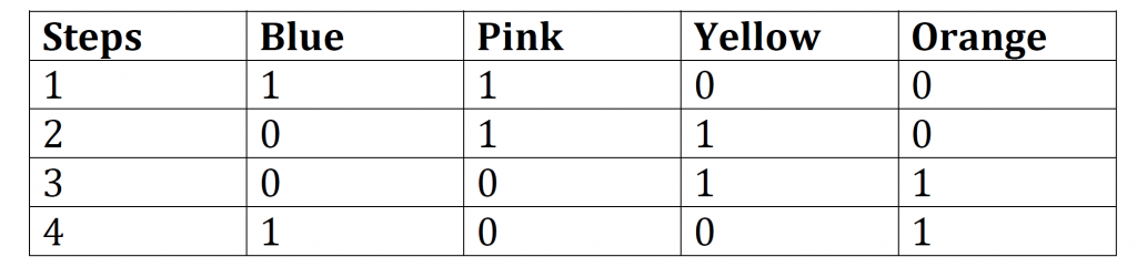
Full Drive : If two stator electromagnets are energized at a time, the motor will run at full torque known as full-drive sequence mode.
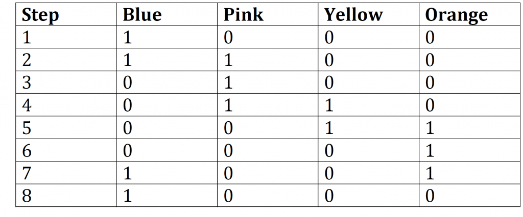
Half Drive : When alternatively one and two phases are energized, the motor will always run in half drive mode. It is used to increase the Angular resolution.
The drawback of this is Half Drive is that :
less torque produced in this movement.
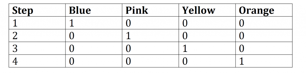
Wave Drive : In this mode, One stator electromagnet is turned on only. It follows 4 steps same as First-drive mode. It consumes low power and also low torque.
By doing this process, the Interfacing of stepper motors with PIC is easily done.
Also read here
https://eevibes.com/engineering-projects/how-to-control-the-direction-of-dc-motor-with-pic/