How to perform subtraction of unsigned numbers in PIC microcontroller?
How to perform subtraction of unsigned numbers in PIC microcontroller? Unsigned numbers can be defined as those numbers in which all the bits in binary format can be used to represent data and no bit can be utilized to show positive or negative sign of the number due to this property of the unsigned numbers, operands can be from 0x00 to 0xFF (0 to 255 in decimal) for 8-bit data.
Subtraction of unsigned numbers
Most of the microcontrollers have two different kind of instructions to perform subtraction: SUB and SUBB (subtract with borrow). But, in PIC 18 there are 4 different kinds of instruction for performing subtraction: SUBLW, SUBWF, SUBWFB, and SUBFWB. The last two are subtract with borrow.
The carry flag C will we used for the purpose of Borrow in PIC now we will demonstrate each instruction.
SUBLW K (WREG = K – WREG)
In subtraction. the PIC microcontrollers (in fact all modern CPUs) use the 2’s complement method. Although every CPU consist of adder circuitry, it might be very inconvenient (and take too many transistors) to design separate subtractor circuitry. For this reason, the PIC uses adder circuitry to perform the subtraction command. supposing that the PIC is executing a simple subtract instruction and that C = 0 prior to the execution of the instructions, the hardware part of CPU perform SUBLW instruction to perform subtraction process by the below mentioned summarized steps:
1. Take the 2’s complement of the subtrahend (WREG operand).
2. Add it to the minuend (K operand).
These two steps are performed for every SUB instruction by the internal hardware of the CPU. In any case of the source of the operands, provided that the addressing mode is supported. It is after these two steps that the result is obtained and the flags are set.
Example 1
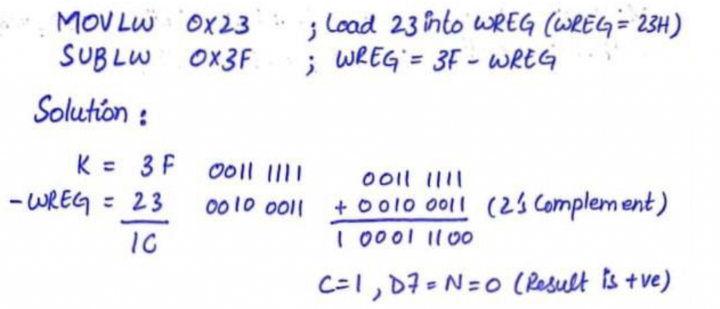
The flags would be so as follows: C = 1, N = 0 (notice that D7 is the negative flag). The programmer must see at the N or C flag to decide if the result is positive or negative.
After the implementation of SUB, if N = 0 (or C = 1), the result is positive; if N = 1 (or C = 0), the result is negative and the destination includes the 2’s complement of the result. Usually, the result is left in 2’s complement form, but the NEGF “negative filereg” (negate, which is 2’s complement) instruction can be used to change it.
One more SUB instruction in PIC is SUBWF (Destination = fileReg – WREG). This is shown in Example 2 together with the NEGF instruction.
Example 2
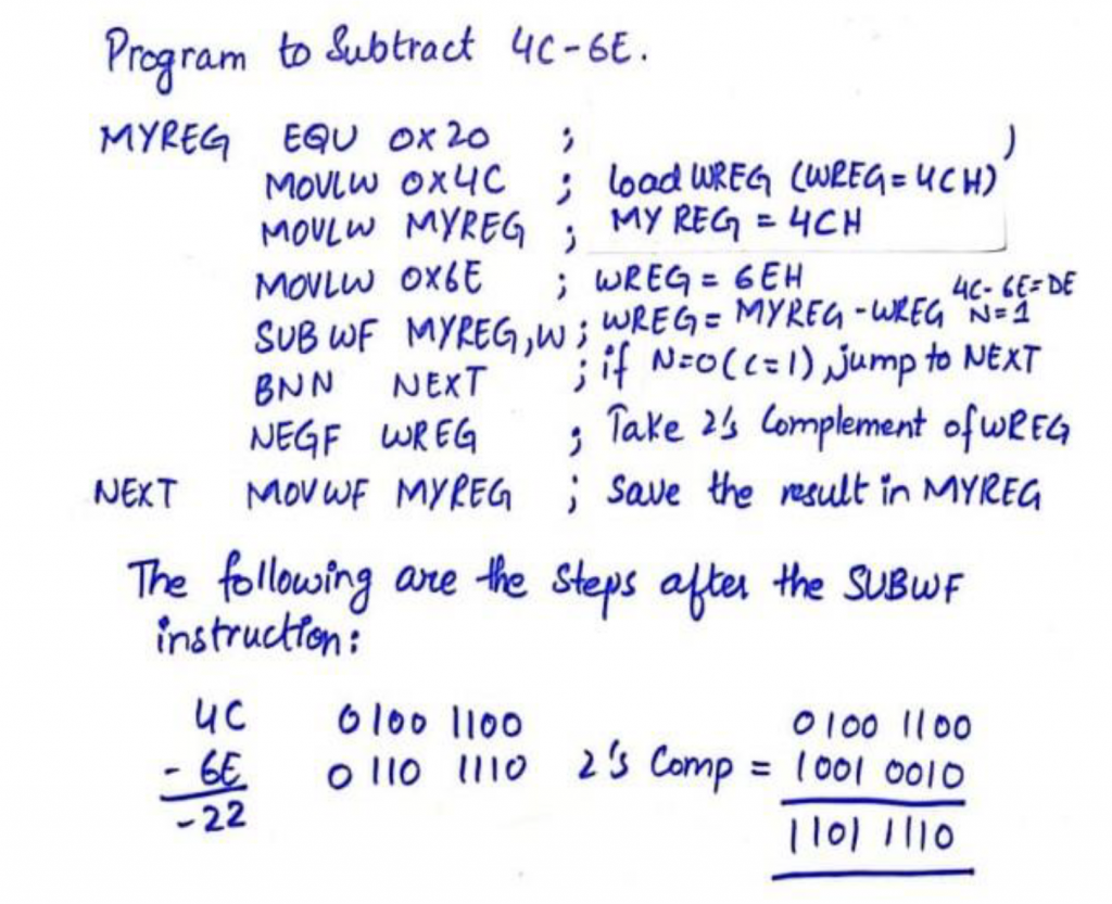
After SUBWF, we’ve N = 1 (or C = 0), and therefore the result is negative, in 2’s complement form. Then it came through and NEGF (Negative FileReg) instruction will be executed. The Negative filereg instruction take the 2’s complement, and then MYREG = 22H.
SUBWFB (dest = fileReg – W – Borrow) subtract with borrow
Syntax SUBWFB f,d,a
This instruction can be used to subtract the working register value and the inverted borrow flag from the filereg value and put the result in working register if the value of “d=0” and to filereg if “d=1”.
Steps by hardware of microcontroller for executing SUBWFB
• take 2’s complement of the working register
• add to the filereg
• add inverted carry flag to the answer
• ignore the carry
• identify the N-Flag for sign of the result
This instruction can even be used for multiple byte containing numbers and will take care of the borrow of the lower byte. If C = 0 earlier to performing/executing the SUBWFB instruction, it also subtracts 1 from the result. See Example 3
SUBFWB (cleat = WREG – fileReg – Borrow)
Syntax SUBFwB f,d,a
This instruction can be used to subtract the filereg value and the borrow/carry flag from the working register value and put the result in working if the value of “d=0” and to filereg if “d=1”.
Steps by hardware of microcontroller for executing SUBWFB
• take 2’s complement of the filereg byte
• add to the working register
• add inverted carry flag to the answer
• ignore the carry
• identify the N-Flag for sign of the result
This instruction can also be used for multiple byte containing numbers and will take care of the borrow of the lower byte
Example 3
Program to subtract two 16-bit numbers. The numbers are 0x2762 – 0x1296. Assume fileReg location 0x6 = (62) and location 0x7 = (27). Put the difference in fileReg locations 0x6 and 0x7; loc 6 should have the lower byte
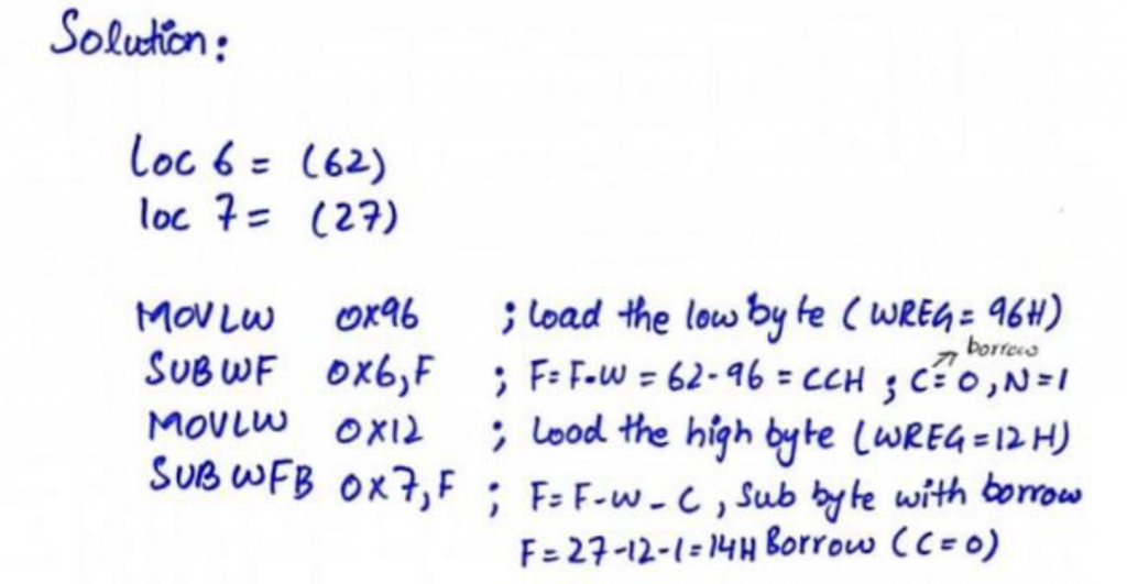
After the SUBWF, loc 6 has = 0x62 – 0x96 = 0xCC and therefore the carry flag is set to 0, indicating there is a borrow (N = 1). Because C = 0, when SUBWFB is executed the fileReg location 7 has = 0x27 -0x12 – 1 = 0x14. Therefore, we have 0x2762 – 0x1296 = 0x14CC.
C Flag in subtraction of PIC
The PIC 18 is different from other microcontrollers such as the 0x86 and the 8051 when it comes to the carry flag in subtract operations. In those microcontrollers, the carry is inverted by the microcontroller itself and we examine the C flag to see if the result is positive or negative. In the PIC 18, if C = 0, the result is negative. That is why in subtract with borrow we have F = F – W as a final result
Also read here for more
What is the maximum frequency signal that can be generated in PIC18F4550 microcontroller?