What is the CCP module of PIC microcontroller?
What is the CCP module of PIC microcontroller? CCP stands for capture, compare pulse width. It is specially used for modulation of waveforms in general applications. Time delays can also be generated by this. It has three modes;
- 16bit capture register
- 16bit compare register
- 10bit PWM master/slave duty cycle registers.
Capture mode
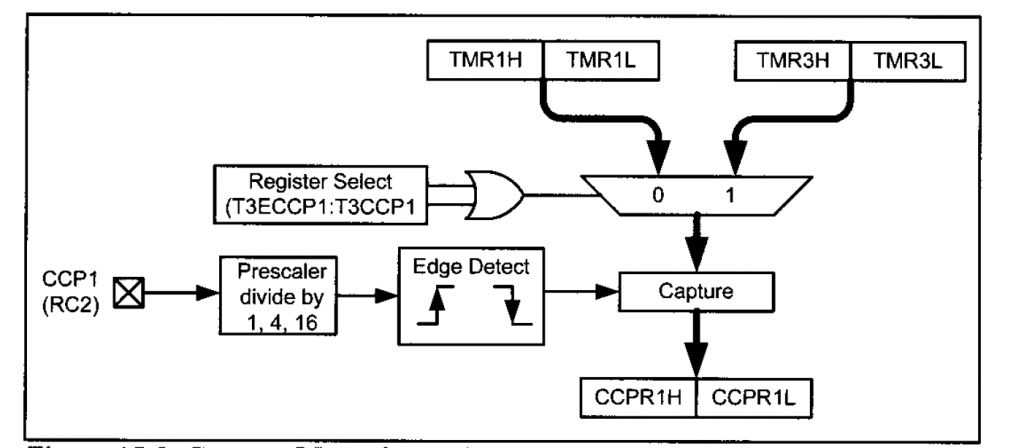
In this mode register constantly changes its value. This mode allows us to access the current state of that register. For this we use TMR1 register.
Compare mode
This mode compares the value of two registers. After a certain time expires, circuit allows the user to trigger an external event.
PWM mode
In this mode we can create waveforms of different frequencies and duty cycles a take output on one or more pins.
CCP1 module of pic micro controllers
it has 16-bit CCPR1 registers which has 8-bit CCPR1L and CCPR1H registers.
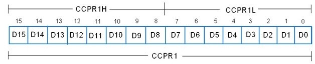
This register stores and compares the binary numbers in timer register.
CCP1CON register
We use this module to select the mode of CCP. It is also known as CCP control register.

CCPxM3: CCPxM0 are used for selection of CCP mode.
CCP1 Capture mode
Timer registers TMR1 an TMR2 are placed in this register. The combination of four bits of these registers determines which of events cause 16-bit data to be transferred.
CCP1 Compare mode
In this mode the value of 16-bit CCPR1 register is compared with the TMR1 register. If value gets matched then state of output pin is changed an interrupt flag is generating.
T3CON register
It is used to select timer1 or timer3 register for compare mode.
CCP1 PWM mode
Pulse width modulation (PWM) is a great technique for controlling analogue circuits with microcontroller digital outputs. If the signal is high, that will indicate the ON time and if it is low, that is the OFF time.
PWM PERIOD of CCP module in pic microcontroller
The output pulse period (T) of waveform is determined by the PR2 register of the timer TMR2. The PWM period can be calculated as:
PWM Period = TPWM = (PR2 +1) * 4*TOSC * TMR2 Pre-scale Value
PROGRAMMING OF CCP module
- RC2 is set as output pin.
- For our required mode of operation CCP1CON = 0x0B.
- Since CCP interrupt will be used, CCP1IE must be set. GIE and PEIE also have to be set.
- We’ll do the toggling in the interrupt service routine (ISR).
- After every 10ms, the state of RC2will be toggled.
Capture mode operation
Also read here
https://eevibes.com/computing/introduction-to-computing/what-is-data-communication-classification/