Implementation of Digital Meters for DC Machines
Implementation of Digital Meters for DC Machines. Measurement is basically a comparison between a quantity to be measured and the standard given quantity of same type selected as a unit. The measurement of a quantity is shown on the scale through a deflection of a pointer. It can also be measured by a numbered scale as well which shows the ration between measured and standard quantity.
A standard can be defined as the physical image of the unit of measurement or it’s multiplying factor. The measuring instrument is defined as the device or instrument which shows the difference between the measured quantity and standard quantity of its type. There are two methods to measure the unknown quantity.
The direct method and indirect method. There is no comparison between measured quantity and standard quantity in direct method of measurement. Direct measurement examples are current, voltage, resistance and power by ampere meter, volt meter, ohmmeter and wattmeter respectively. In indirect method the measured valve can be calculated from mathematical equation from other quantities. For example the resistance can be measured by the Ohm’s equation.
R=V/I
Measurement Standards:
There are different standards for different amounts.
The Current Standard
The last unit of electric current is (ampere) and defined unit (SI) the constant current which, if it is maintained in two straight parallel conductors of infinite length and insignificant circular circular section, is placed a meter of the vacuum will produce between these conductors a strength of 2 × 10⁻⁷ newton per meter in length. The first measurements of the absolute value of the ampere were made with current balancing that measures the force exerted between two parallel conductors.
Throughout the world, the value of the global amplifier was based on the silver electrolyte deposition of a silver nitrate solution. The ampere SI is defined as the current that deposits silver at a speed of 1,118 mg / sec from a standard solution of silver nitrate. However, the exact measurement of silver deposits poses some problems. Therefore, it is changed with an absolute amplifier. Now, in the SI system, the current unit is the absolute amp and is accepted globally by an international contract.
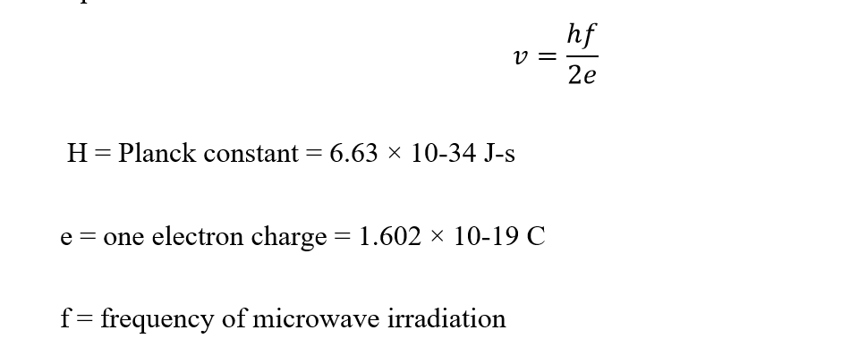
The Voltage Standard
At the beginning of time, the standard volt was based on an electrochemical cell called the standard saturated cell treated as a standard cell. But this cell depended on the temperature, its output voltage deviations of about -40 μV / ° C compared to the nominal value of 1.01858 volts. The standard cell is dying due to this temperature dependence and because the voltage is a function of a chemical reaction and is not directly related to other physical constants. In 1962, Brian Josephson introduced the new standard for tension. It was a thin film joint and cooled to approximately the absolute temperature and the exposed microwave energy. A voltage develops at the junction, which is associated with its radiation frequency according to the following equation.
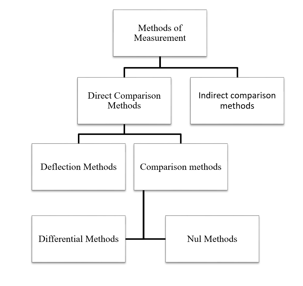
Methods of Measurement:
There are two measurement methods.
- Direct comparison methods
- Indirect comparison methods
Direct Comparison Methods
In direct measurement methods, the unknown quantity is measured directly. The methods of direct measurement are of two types, namely, methods of deviation and methods of comparison.
In the deviation methods, the value of the unknown quantity is measured by means of a measuring instrument that has a calibrated scale that directly indicates the measured quantity, such as measuring the current by means of an ammeter. In comparison methods, the value of the unknown quantity is determined by a direct comparison with a standard of the given quantity, such as the measurement of the comparison of the emf with an emf of a standard cell. The comparison methods can be classified as null methods, differential methods, etc. In null measurement methods, the action of the unknown quantity in the instrument is reduced to zero by the opposite action of a known quantity of the same type, such as the measurement of the weight per balance, a measure of the resistance, capacitance and inductance by bridge circuits.
Indirect Comparison Methods
In indirect measurement methods, the comparison is made with a standard that uses a calibrated system. These measurement methods are used in cases where the parameter to be measured is difficult to measure directly, but the parameter has a relationship with another associated parameter that can be easily measured. For example, the removal of bacteria from a fluid depends directly on its temperature. Therefore, the elimination of bacteria can be measured indirectly by measuring the temperature of the fluid.
In indirect measurement methods, it is common to establish an empirical relationship between the actual measured quantity and the desired parameter.
The different measurement methods are summarized using a tree diagram.
Measuring Instruments and its types
Measurement System & Its Elements
A measurement system may be defined as a systematic arrangement for the measurement or determination of an unknown quantity and analysis of instrumentation. The generalized measurement system and its different components/elements are shown as follows.
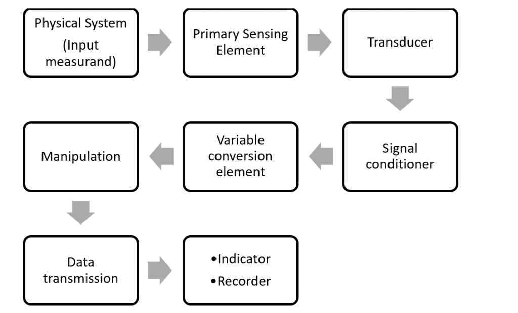
The operation of a measurement system can be explained at the level of the functional elements of this system. Each instrument and measurement system consists of more than one element of this type and of what is:
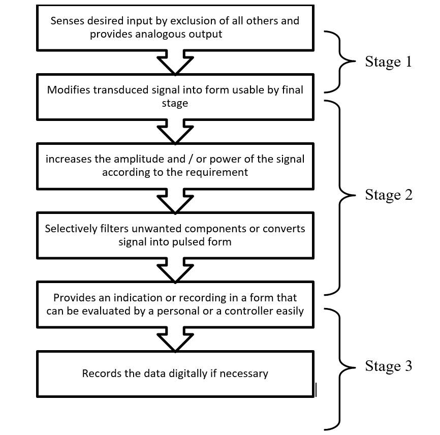
Primary Sensing Elements
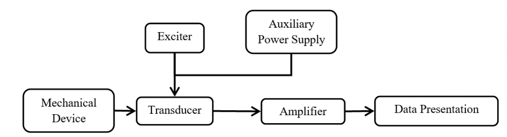
It is an element sensitive to the measured variable. The physical quantity that is measured, called measurand, establishes its first contact with the main sensor element of a measurement system. The measurand is always disturbed by the act of measurement, but good instruments are designed to minimize this effect. The primary sensing elements may have a non-electrical input and output, such as a spring, a pressure gauge, or may have an electrical input and output, such as a rectifier. If the main sensor element has a non-electrical input and output, it is converted into an electrical signal by means of a transducer. The transducer is defined as a device that, when activated by a form of energy, can convert it into another form of energy.
Many times, certain operations must be performed on the signal before its subsequent transmission so that the interfering sources are suppressed so that the signal is not distorted. The process can be linear, such as amplification, attenuation, integration, differentiation, addition and subtraction, or non-linear, such as modulation, detection, sampling, filtering, deletion and trimming, etc. The process is called signal conditioning. Therefore, a signal conditioner follows the main sensor element or the transducer, as the case may be. The sensor element detects the condition, status or value of the process variable by extracting a small part of the measurement energy and then produces an output that reflects that condition, state or measurement value.
Variable Conversion Elements
After passing through the main detection element, the output has the form of an electrical signal, which may be a voltage, a current, a frequency, which may or may not be accepted by the system. To perform the desired operation, it may be necessary to convert this output to another suitable form while preserving the information content of the original signal. For example, if the output is in analog form and the next step in the system only supports digital, an analog to digital converter will be used. Many instruments do not require a variable conversion unit, while others require more than one element.
Manipulation Elements
Sometimes it is necessary to change the level of the signal without changing the information it contains for the acceptance of the instrument. The function of the variable manipulation unit is to manipulate the signal presented to it while preserving the original nature of the signal. For example, an electronic amplifier converts a small low-voltage input signal into a high-voltage output signal. Thus, the voltage amplifier acts as a variable manipulation unit. Some instruments may require this function or others may not work.
Data Transmission Elements
The data transmission elements are obliged to transmit the information of the signal information from one system to another. For example, satellites are located near the Earth where the control stations that guide their movement are located.
Data Presentation Elements
The function of data presentation elements is to provide an indication or record in a form that can be evaluated by a human sense without help or by a controller. The information on the measurand (quantity to be measured) must be transmitted to the personnel that manage the instrument or system for monitoring, control or analysis. Said device can have the form of analog or digital format. The simplest form of a display device is the common panel display with a kind of calibrated scale and pointer. If the data is to be recorded, recorders such as magnetic tapes or magnetic disks can be used. For control and analysis, computers can be used.
The steps of a typical measurement system are summarized below using a flowchart
Classification of Instruments
The measuring instruments can be classified as follows:
Absolute and secondary instruments.
Absolute Instruments.
Instruments of this type give the value of the measurand in terms of the instrument’s constant and its arrow. These instruments do not require comparison with any other standard. The example of this type of instrument is the tangent galvanometer, which provides the value of the current to be measured in terms of tangent to the angle of deviation, the horizontal component of the Earth’s magnetic field, the radius and the number of turns of the wire used The Rayleigh current balance and the absolute electrometer are other examples of absolute instruments. Absolute instruments are used mainly in standard laboratories and similar institutions. The classification of the measuring instruments is illustrated in the figure.
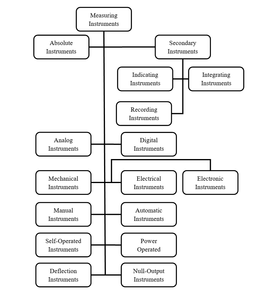
Secondary Instruments
These instruments are constructed in such a way that their deviation directly indicates the magnitude of the electrical quantity to be measured. These instruments should be calibrated compared to an absolute instrument or other secondary instrument already calibrated before use. These instruments are generally used in practice.
Secondary instruments are also classified as
Indicating instruments
Integration instruments
Recording instruments
Indicating Instruments
The indicator instruments are those that indicate the magnitude of an electrical quantity at the time it is measured. The indications are given by a pointer that moves on a calibrated scale (pre-graduated). Ammeters, voltmeters, watt meters, frequency meters, power factor counters, etc. are included in this category.
Integrating Instruments
The instruments of integration are those that measure the total amount of electricity (ampere-hours) or electric power supplied during a given period. The sum, given by such an instrument, is the product of time and the electrical quantity that is measured. Ammeters and energy meters fall in this class.
Recording Instruments
Recording instruments are those that maintain a continuous record of the variation in the magnitude of an electrical quantity that must be observed during a defined period of time. In such instruments, the moving system carries a pen with ink that lightly touches a sheet of paper wrapped in a drum that moves with a slow and uniform motion in a direction perpendicular to that of the pointer. In this way, a curve is drawn showing the changes in the magnitude of the electrical quantity observed during a defined period of time. These instruments are generally used in power plants where current, voltage, energy, etc. It must be kept within certain acceptable limits.
Analog and Digital Instruments
Analog Instruments
The signals of an analog unit vary continuously and can take an infinite number of values in a given range. Metter of fuel, am meter and volt meter, wristwatch, speedometer in this category.
Digital Instruments
Signals that vary in discrete steps and that take a finite number of different values in a given range are digital signals and the corresponding instruments are digital. Digital instruments have some advantages over analog meters, since they have a high precision and a high speed of operation. Eliminate human operational errors. Digital instruments can store the result for future purposes. A digital multi meter is the example of a digital instrument.
Mechanical, Electrical and Electronics Instruments
Mechanical Instruments
The mechanical instruments are very reliable for static and stable conditions. They can not react quickly to the measurement of dynamic and transient conditions because they have rigid, heavy and bulky moving parts and, consequently, a large mass. The mass poses problems of inertia and, therefore, these instruments cannot faithfully follow the rapid changes inherent in dynamic instruments. In addition, most mechanical instruments cause noise.
Advantages of Mechanical Instruments
- Relatively cheaper cost
- More durable due to its robust construction
- Simple in design and easy to use
- Does not require external power for the operation
- Reliable and accurate to measure a stable and invariant amount over time
Disadvantages of Mechanical Instruments
- Poor frequency response to transient and dynamic measurements.
- Significant force required to overcome mechanical friction.
- Incompatible when control and remote indication is needed
- cause noise pollution
Electrical Instruments
When the deviation of the indicator of the instrument is caused by the action of certain electrical methods, it is then spoken of an electrical instrument. The operating time of an electrical instrument is faster than that of a mechanical instrument. Unfortunately, an electrical system usually depends on a mechanical measurement as an indicator device. This mechanical movement has a certain inertia because the frequency response of these instruments is mediocre.
Electronic Instruments or Digital Instruments
Electronic instruments use semiconductor devices. Most scientific and industrial instrumentations require very fast answers. These requirements cannot be met by mechanical and electrical instruments. In electronic devices, the only movement in question is that of electrons, the response time is extremely low due to the very low inertia of the electrons. With the use of electronic devices, a very weak signal can be detected using preamplifiers and amplifiers.
Advantages of Electrical/Electronic Instruments
- Non-contact measurements are possible
- These instruments consume less energy.
- Compact size and most reliable operation.
- Greater flexibility
- Good frequency and transient response.
- Remote indication and possible recording.
- Amplification produced superior to that produced in a mechanical instrument.
Manual and Automatic Instruments
In the case of manual instruments, the service of an operator is required. For example, to measure the temperature with a resistance thermometer that incorporates a Wheatstone bridge in its circuit, an operator must indicate the measured temperature.
In an automatic instrument type, no operator is required at any time. For example, measure the temperature with a glass mercury thermometer.
Self-operated and Power-operated Instruments
Automatic control instruments are those in which no external power is required for their operation. The output energy is provided totally or almost completely by the input measurand. Dial-type instruments belong to this category.
Motorized instruments are those in which an external power source such as electricity, compressed air or hydraulic energy is needed for its operation. In this case, the input signal provides only a negligible part of the output power. An electromechanical instrument shown fell into this category.
Deviation instruments and zero outputs
In a deviation type instrument, the deviation of the instrument indicates the measurement of the unknown quantity. The measured quantity generates a physical effect that deflects or produces a mechanical displacement in the movement system of the instrument. An opposite effect is incorporated into the instrument that opposes deflection or mechanical movement of the moving system. The equilibrium is reached when the opposite effect is equal to the cause of the action produced by the deviation or mechanical displacement. The deviation or mechanical displacement at this point gives the value of the unknown input quantity. These types of instruments are suitable for measurement under dynamic conditions. Examples of these are permanent magnet moving coil (PMMC), moving iron (MI), etc.
In null-type instruments, a null or zero indication leads to the determination of the magnitude of the measured quantity. The null condition depends on other known conditions. These are more accurate and very sensitive compared to deviation type instruments. A DC potentiometer is a null type instrument.
Definitions of Some Static Characteristics
Accuracy
The precision is the proximity with which the reading of the instrument is close to the real value of the variable that is measured. The precision is the maximum amount so the result differs from the real value. It is almost impossible to determine true value experimentally. The true value is not indicated in any management system due to the effects of loading, delays and mechanical problems.
The accuracy of the signal depends on the following factors:
- intrinsic accuracy of the instrument itself;
- observer accuracy;
- variation of the signal to be measured; Y
- If the quantity is actually printed on the instrument.
Precision
Precision is a measure of the reproducibility of measurements, that is, accuracy is a measure of the extent to which successive measurements differ from each other. The precision is indicated by the number of significant digits in which it is expressed. Significant digits actually convey information about the magnitude and measurement accuracy of a quantity. The most significant figures imply a greater precision of measurement.
Resolution
If the input slowly increases from an arbitrary value, it will be noted that the output does not change at all until the increase exceeds a certain value called resolution or discrimination of the instrument. Therefore, the resolution or discrimination of any instrument is the smallest change in the input signal (the amount that is measured) that can be detected by the instrument. It can be expressed as an acquisition value or as a fraction or percentage of the total value. The resolution is sometimes called sensitivity. The largest change in the amount of input for which there is no instrument output is called the dead zone of this instrument.
Sensitivity is the relationship between the input signal to an instrument or part of the instrument system and the output. Therefore, sensitivity is defined as the ratio of the output signal or the response of the instrument to a change in the input signal or the quantity being measured.
Speed of Response
The speed with which an instrument reads the measurement variable is called the response speed. Alternatively, the response speed is defined as the time elapsed between the start of the measurement and the reading. This time depends on the system of mechanical displacement, friction, etc.
Also read here
https://eevibes.com/electronics/electronic-circuits/design-an-arduino-based-gas-leakage-detector/