What is DAC interfacing?
What is DAC interfacing? The definition of Digital to Analog Converter (DAC) is that it a device that converts a digital input signal into an analog output signal. Basically, the digital signal is usually represented by a binary code, which is the combination of bits, 0 and 1.
Techniques:
There are usually many techniques in which this method is done, each with its own pros and cons.
Methods:
Generally, there are two methods for the conversion of digital signals to the analog signals. Thus, these two methods are the binary weighted methods and the R/2R ladder method.
DAC Working:
The binary system is basically a positional system which is a place value system, with having each bit representing or showing the presence and the absence of a particular power of two in the total sum of the powers.
In other words, the whole process or method of digital to analog conversion can also be thought of as a Scaling Operation, so the binary count is usually drawn to a basic certain voltage range, with having 0V being the minimum and the maximum voltage being the maximum input binary voltage.
Types of DAC’s:
- Weighted Resistor DAC
- R-2R Ladder DAC.
Weighted Resistor DAC:
A weighted resistor DAC usually generates an analog output, basically which is nearly equal to the digital (binary) input through using the binary weighted resistors in the inverting adder circuit.
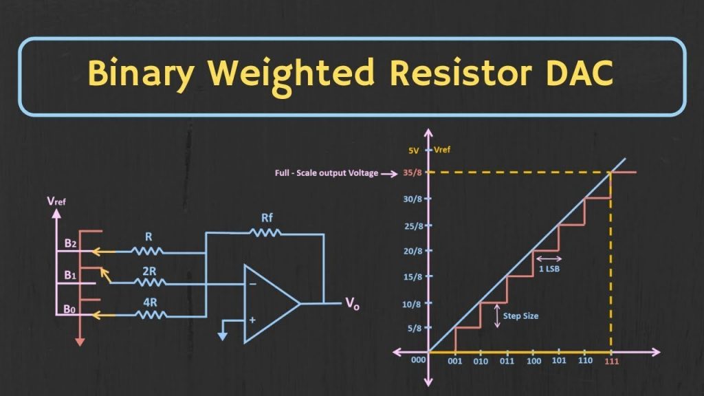
Drawbacks:
There are some drawbacks of the binary-weighted DAC which are that it has a quite large gap between the LSB and the MSB resistors values and it also requires a very precise value of resistors.
It also becomes impractical for the higher-order DAC’s and thus it is suitable for the DAC’s having less resolution.
Basically, the consistency or strength of the device is the resistor-dependent and thus is difficult to maintain an accurate and precise resistance ratio with the temperature variations.
Advantages:
There are some advantages:
It has a basic simple assembly.
It has fast conversion speed.
There is the simple conversion circuit.
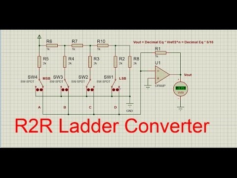
R-2R Ladder DAC:
The R-2R Ladder Digital-to-Analogue Converter, or DAC, is basically a data converter which usually use two precision resistors to convert and change a digital binary number into an analogue output signal which is proportional to the value of the digital number.
Drawbacks:
There are some drawbacks of R-2R Ladder DAC:
This type usually requires a large range of resistors with required high precision for low resistors. It also requires the low switch resistances in the transistors
It also has slow conversion speed.
Advantages:
There are some advantages which are as follows:
This device can be easily fabricated.
Thus, the configuration basically needs the only two resistors with one being twice the other in the value instead of a wide range of resistors.
Hence, the output resistance remains the same despite the number of bits.
And the increase in the resolution do not degrade the performance.
Applications of DAC’s:
The applications of DAC’S are as follows:
-
Digital Signal Processing
The Digital Signal Processing is much easier to work with the signals once they have been converted or changed to the binary.
An example of this processing is the audio editing. In Audio Editing, basically the audio is converted into the binary after which the operations can be performed on it. Thus, in order to play back this audio, a DAC is thus used to change it into a sound signal that can also be played back on a speaker.
-
Digital Power Supplies
The most microcontrollers are usually too slow to be a part of a power supply control loop. Thus, to change or convert the voltage or current of a power supply, so that a reference can be changed. This can be done basically by connecting a DAC to the output of a microcontroller and then by using that to change or convert the reference voltage to a pre-selected value.
Drawbacks of DAC’s
- Accuracy:
Thus, the DAC’s can only produce as much voltage steps as the binary number will allow to it, hence in other words it is almost impossible to produce the truly continuous voltage values.
- Complexity:
Thus, most of the DAC requires a few parts and this may not always be practical.
How to Program in DAC in C:
It involves the use of the MC1408 (DAC0808) Digital to Analog Converter. Basically, in this chip a R/2R ladder method is used. Basically, this method or procedure can attain a much higher degree of precision. Thus, the DACs are judged by their resolution. Thus, the resolution is a function of the number of the binary inputs. Hence, the most common input counts are 8, 10, 12 etc. The number of data inputs basically decides the resolution of DAC. Therefore, if there are n number of digital input pin, then there are 2n analog levels. Thus, 8 input DAC has basically 256 discrete voltage levels.
The MC1408 DAC (or DAC0808):
So, in this chip the digital inputs are converted and changed to the current. The output current is basically known as the I out by connecting a resistor to the output to convert or change it into voltage. Thus, the total current provided by the I out pin is basically a function of the binary numbers at the input pins which are D0 – D7 (D0 is the LSB and D7 is the MSB) of DAC0808 and the reference current I ref. Here the following formula is showing the function of I out:
I out=I ref ⟮D72+D64+D58+D416+D332+D264+D1128+D0256⟯
Here the I ref is the input current. So, this must be provided into the pin 14. Usually, the 2.0mA is used as the I ref.
Then, we connect the I out pin to the resistor so that to convert the current into the voltage. But in the actual life it may also create inaccuracy as the input resistance of the load will also cause an effect to the output voltage. Therefore, practically I ref current input is thus isolated by connecting it to an Op-Amp with Rf = 5KΩ as the feedback resistor. Basically, the feedback resistor value can be changed as per as the requirement.
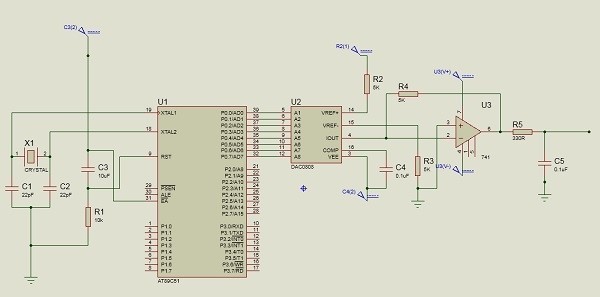
Generating Sinewave using DAC and 8051 Microcontroller:
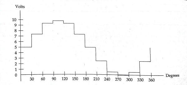
So, for generating a sinewave, first basically we need a look-up of the sine value of angles between 0° to 360° and other parameters for DAC. Basically, the sine function varies from -1 to +1. The integer values are basically applicable for the DAC input. In an example we will only consider 30° increments and then calculate the values from the degree to DAC input. Thus, we are assuming the full-scale voltage of 10V for the DAC output. However, we can also follow this formula to get the voltage ranges which is as follows:
V out = 5V + (5 ×sinθ)
Circuit Diagram :
Programming DAC in C:
#include<reg51.h>
sfr DAC = 0x80; //Port P0 address
void main(){
int sin_value[12] = {128,192,238,255,238,192,128,64,17,0,17,64};
int i;
while(1){
//infinite loop for LED blinking
for(i = 0; i<12; i++){
DAC = sin_value[i];
}
}
}
Also read here