
Introduction
Cross Talk Noise Reduction in Synthesized Digital Logics. In this article we have discussed crosstalk noise reduction by several different methods. Gate sizing is normally practical and feasible but the difficulty in this process for noise reduction is increasing by size of the driver can create noise violation, but by post route gate sizing algorithm that use a graph representation of the noise dependencies between nodes is very fast and effective way for crosstalk noise reduction. Another method is post layout transistor sizing method through this process noise voltage is reduced by more than 50% but the risk is also involved of crosstalk noise problem. There is also another way cost of noise reduction that is synthesis methodology using this my third or a design flow timing uncertainty was reduced to below 3% and power penalties and area below 20%.
What is the Crosstalk?
Crosstalk is the impedance between signals that are proliferating on different lines in the framework. Crosstalk results from the cooperation of electromagnetic fields produced by adjoining information signals as they proliferate through transmission lines and connectors. Crosstalk noise problem is a major problem that completely depends on the interconnect formation, i.e., coupling length spacing between neighboring wires and coupling positions hence many methods of routing and interconnect optimization for crosstalk noise reduction are proposed.
Insertion of buffer is also proposed for noise reduction. Gate sizing and post layout transistor sizing are also used for crosstalk noise reduction. Development of an optimized algorithm is used for crosstalk noise reduction that give us room to explain solution space efficiently, under delay constraint and by using noise estimation method we can also produce a crosstalk noise reduction method and Tr sizing framework.
All the methods mentioned above have limited effectiveness, so introduction of a new post route gate sizing is used that help us in crosstalk noise reduction, but the major problem of post route gate is non-linear dependence and due to this it is impossible to solve non-linear optimization so heuristic algorithm is introduced.
As we go deep into crosstalk noise reduction digital noise is also becoming a benchmark and due to this CMOS and VLSI system are designed. A design flow is proposed for automatically synthesizing CMOS circuits that also help us to improve quality of noise effect.
Crosstalk-History
Crosstalk noise optimization by post-layout transistor sizing technique is in view of a crosstalk noise mindful static timing examination. Despite the fact this technique changes circuits extensively, format alterations are not thought about. This paper proposes a post-design semiconductor measuring technique for crosstalk sound decreases.
The proposed technique upgrades detailed routed circuits saving interconnects completely. The interconnect data expected for crosstalk commotion assessment can be totally acquired after detail-steering. The enhancement consequence of semiconductor measuring can be applied to the design totally on the grounds that the proposed technique uses the semiconductor measuring structure that can scale back the semiconductors inside cells saving interconnects.
This structure is initially produced for power decrease. In this paper, we utilize this system for crosstalk noise decrease. In this system, different driving-strength cells are created on the fly as indicated by the enhancement result, and consequently transistor level streamlining can be executed in cell-based plans. Cell designs are produced by a design age framework called VARDS. VARDS depends on an emblematic format strategy and is upgraded to deliver cell designs with variable driving strength. Taking advantage of this system, the proposed strategy diminishes crosstalk commotion productively after detail-steering. Concerning crosstalk noise assessment, our technique uses a 2-pie noise model with further developed aggressor displaying
Therefore, a novel post-route gate sizing approach for crosstalk noise reduction in this study. Due of crosstalk noise’s non-linear reliance on the connection Post route gate sizing for crosstalk noise reduction is a non-linear optimization problem that depends on driver characteristics. Today’s highly connected interconnects have a colossal system size, making it impossible to solve the nonlinear optimization problem precisely. In this study, we suggest a heuristic algorithm.
The algorithm reduces the size of the aggressive drivers while increasing the size of the victim drivers. The suggested approach handles each net as both an attacker and a victim while taking into account timing and spatial restrictions. This duality is a crucial consideration in post-route gate sizing and must be taken into account to prevent the introduction of new noise violations while xing current faults. We approach the issue by providing a noise graph that is built using the design’s static noise analysis.
All important nets, their significant aggressors, and the relationships between them in the noise graph are represented. In order to reduce system complexity, we create a sensitivity metric to remove weak dependencies from the noise graph. A cyclic sensitivity metric is used to analyze the significant cyclic dependencies in the noise graph. Although high sensitivity cycles are removed from the graph by deleting a minimal number of vertices, cycles that are likely to converge are permitted to stay in the graph. To create an acyclical graph, some edges from the low sensitivity cycles are momentarily eliminated. The next step is to sort the resultant acyclical graph topologically, where the topology of the noise graph stands in for the noise dependence links. After that, gate sizing is iterated.
Digital noise is also becoming a benchmark as we go deeper into crosstalk noise reduction, and as a result, CMOS and VLSI systems are created. For automatically generating CMOS circuits, a design procedure is put forth that also aids in enhancing the quality of the noise effect.
Methodology
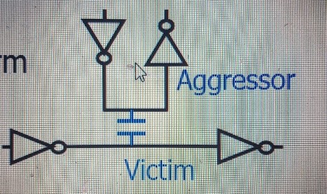
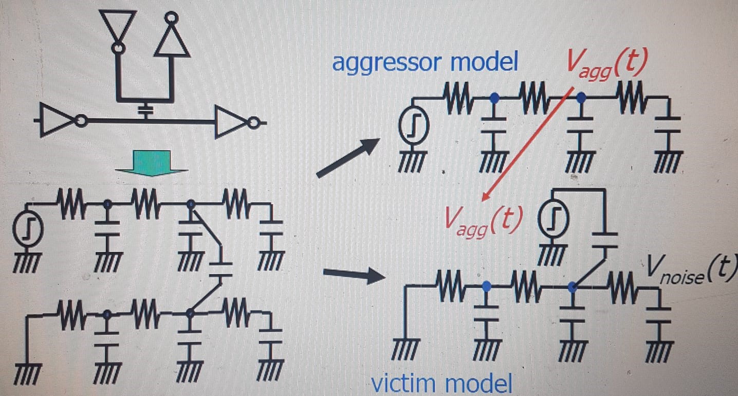
We provide a brief explanation of the suggested technique, which uses the 2-pie noise model to estimate crosstalk. We then go through a noise estimate technique based on superposition that takes temporal window into account for a net with numerous aggressors.
Overview of crosstalk noise reduction:
Multiple Aggressors, multiple branches,
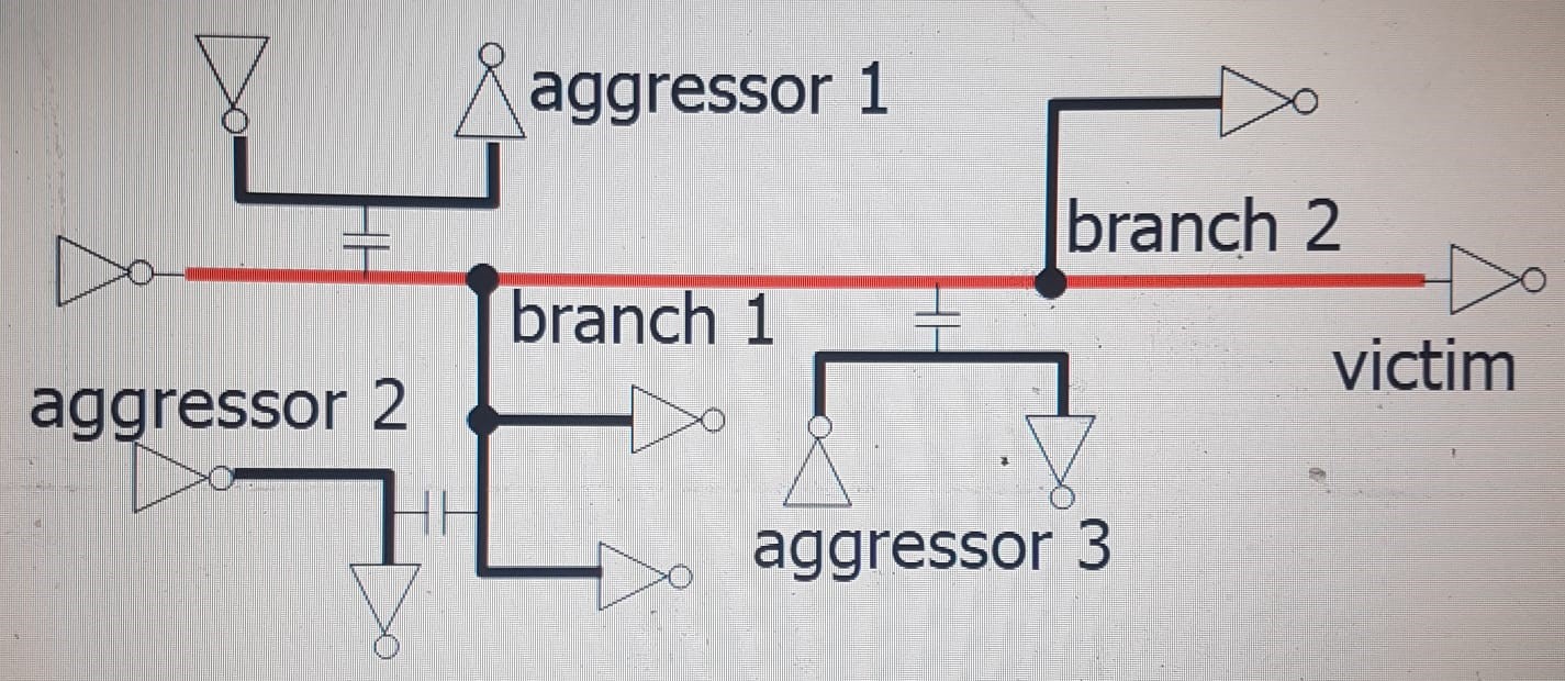
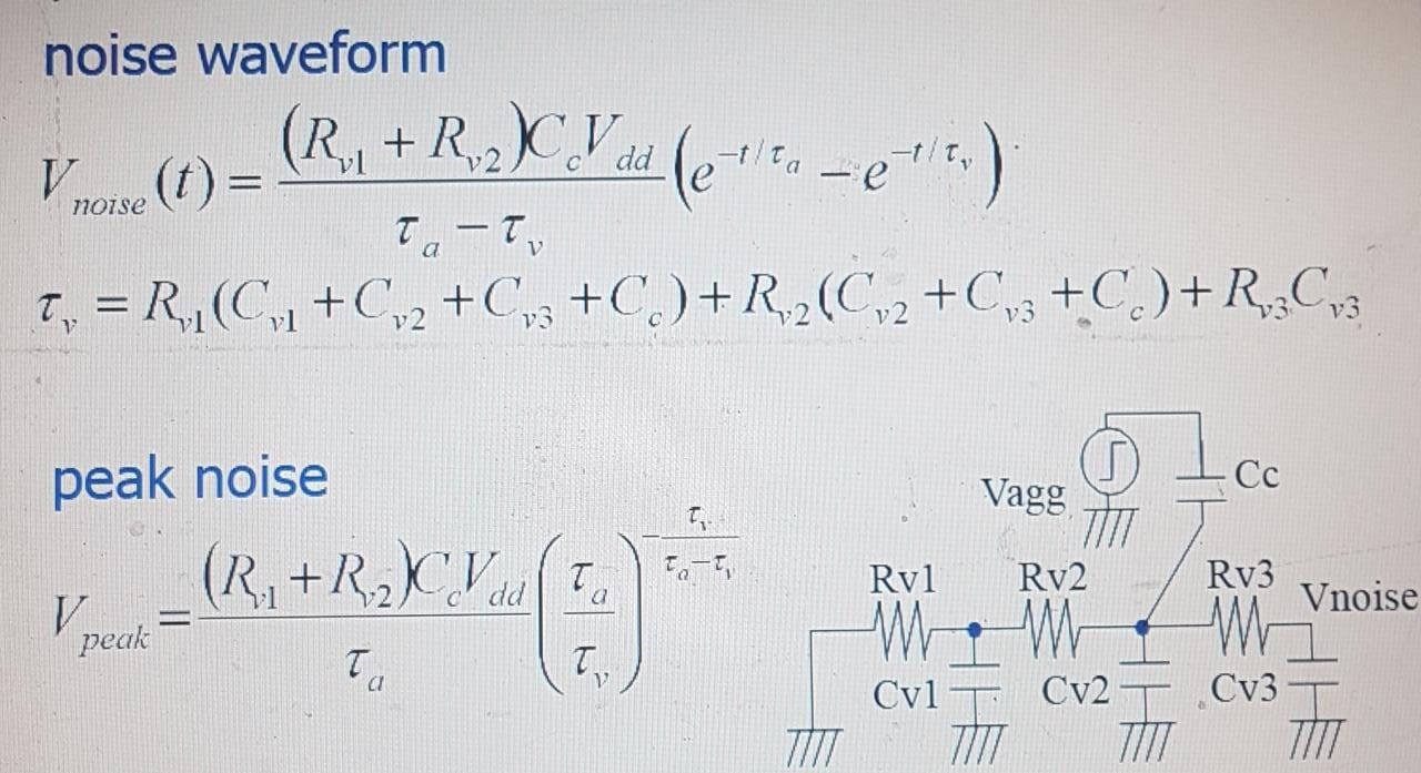
- Closed-form noise waveform noise estimation for two partially connected interconnects
- Noises from each aggressor are superimposed by more aggressors.
- Multiple sinks become two interconnects that are only partially linked
- Crosstalk Summary of Noise Estimation Attacker Victim
Overall Optimization Algorithm
- First, figure out the crosstalk noise at each circuit net.
- Find the circuit’s maximum crosstalk noise voltage, or Vmax, and add the networks to the candidate list Lo whose noise voltages above Vmax * threshold.
- Stage 3: Select the network in the list Lo that has the highest noise voltage, and carry out the optimization as described The optimization’s target value is the value of the Vmax * threshold. Update the time window information and remove the net from the list Lo.
- Stage 4: Complete the optimization process if the list Lo becomes empty.
- Alternatively, return to Stage 3.
A quick and efficient heuristic technique for post route gate sizing that makes use of a graph representation of the noise dependencies between nodes. Our approach uses gate sizing in both directions and progresses linearly with the number of gates. The algorithm’s effectiveness is demonstrated on a number of industrial high performance designs
Noise Graph Representation
A noise graph G (V; A); E)) has edges E and vertices (V; A):
- Vertices: In the noise graph, vertices stand in for nets. Vertices come in two varieties: Nets that have failed or are on the verge of failing the noise analysis are represented by type V vertices. In other words, type V vertices will be present in nets with noise slack lower than a predetermined positive Drivers with vertices of type V are suitable for sizing up.
- Vertices of type A represent significant aggressors with minimal noise. An aggressor who makes up at least 20% of the overall noise on a victim net is considered a significant aggressor. A network with very little noise has more noise slack than previously measured positive
- Edges: A directed edge exists between vertex a and vertex b if net a significantly aggravates net b. Take note that type A vertices have an in-degree of 0 at all times.
Sizing Algorithm
The pseudo-code of the proposed algorithm is shown below:
Input: Noise analysis results
Output: Instance cell replace directives begin
1 Construct a noise graph G = ((V; A); E) based on noise analysis
2 Size down type A vertices(G) 3 Analyze cycles(G) 4 Break cycles(G)
5 Gs = Topologic sort(G) 6 repeats until convergence
7 for each vertex v in Gs’ 8 Size up(v)
End
Future Work
What can be done to reduce the noise caused by crosstalk?
Crosstalk mitigation techniques
- Minimum width among traces.
- Keep traces on adjacent layers perpendicular.
- Use ground planes.
- Exploit ground return path.
- Use differential signals.
- Reduce the width of parallel traces.
- Isolate high frequency signals from other traces.
- Isolate asynchronous signals.
Conclusion
Above discussion conclude that the crosstalk noise reduction by transistor sizing re can reduced the maximum noise voltage by more than 50% without delay increment after detailed routing and it is also discussed that the fast and effective post route gate sizing algorithm that is done by graph representation of the noise dependencies between nodes and it also shows industrial high performance.