What are the binary logic levels and high impedance states?
What are the binary logic levels and high impedance states? Logic gates are electronic circuits that regulate on one or more input signals to produce an output signal. Electrical signals such as voltages or currents prevail as analog signals having values over a given continuous range, say, 0 to 3 V, but in a digital system, these voltages are defined to be either of two recognizable values, 0 or 1. When below the low limit, the signal is 0. When above the high limit, the signal is 1. Intermediate levels are undefined, occurring in highly implementation-specific circuit behavior.
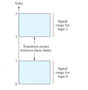
For example, a certain digital system may define logic 0 as a signal equal to 0 V and logic 1 as a signal equal to 3 V.A voltage of 1 to 2 volts would be ineffective and occur merely in a fault situation or during a logic level transition. Regardless, few logic circuits can recognize such a condition, and most devices will interpret the signal simply as high or low in an undefined or device-specific manner.
In practice, each voltage level has a proper range, as shown in diagram. The input terminals of digital circuits receive binary signals and give respond to the output terminals with binary signals that lies within the valid range. The middle region between the allowed regions is crossed only during a state transition. Any needed information for computing or control can be operated on by passing binary signals through different combinations of logic gates, with each signal representing a unique binary variable. When the physical signal is in a specific range it is defined to be either a 0 or a 1.
Interconnecting different logic levels:
Almost all digital circuits use a compatible logic level for all internal signals. That level, though, varies from one system to another. Interconnecting any two logic families frequently required special strategies such as additional pull-up resistors or purpose built interface circuits known as level shifters. A level shifter connects one digital circuit that operates one logic level to another digital circuit that utilizes another logic level. Frequently two-level shifters are utilized, one at each system.
Example:
TTL levels are different from those of CMOS. Normally, a TTL output doesn’t increase high enough to be reliably identified as a logic 1 by a CMOS input, especially if it is only connected to a high-input-impedance CMOS input that does not source considerable current. This issue was solved by the innovation of the 74HCT family of devices that adopts CMOS technology but TTL input logic levels. These devices only operate with a 5 V power supply.
What is the high impedance state?
A three-state logic level, has three outputs. These outputs are as follow: 1, 0 , and “Hi-Z,” or “open.” The hi-Z state is a high-impedance state in which the output is disconnected, leaving the signal open is to be run by another device (to be pulled up or down by a resistor provided to prevent an undefined state).
Application:
High-impedance schemes such as three-state are commonly used for a bus, in which various devices can be chosen to drive the bus.
Also read here
https://eevibes.com/computing/introduction-to-computing/what-are-number-systems/