What is the Consensus Theorem?
What is the Consensus Theorem? The consensus or resolvent of the phrases AB and A’C is BC. It is the conjunction of all of the particular literals of the phrases, with the exception of the literal that looks un-negated in a single time period and negated withinside the other.
The conjunctive twin of this equation is:
(A+B). (A’+C). (B+C) = (A+B). (A’+C)
In the second one line, we pass over the 1/3 product time period BC. Here, the time period BC is called Redundant time period. In this manner we use this theorem to genuinely the Boolean Algebra.
Conditions for making use of Redundancy theorem are:
Three variables ought to gift withinside the expression. Here A, B and C are used as variables. Each variable is repeated twice. One variable ought to found in complemented form. After making use of this theorem, we will simply take the ones phrases which includes the complemented variable.
Proof – We also can show it like this:
Y = AB + A’C + BC
Y = AB + A’C + BC.1
Y = AB + A’C + BC. (A + A’)
Y = AB + A’C + ABC + A’BC
Y = AB (1 + C) + A’C (1 + B)
Y = AB + A’C
Example-1.
F = AB + BC’ + AC
Here, we’ve got 3 variables A, B and C and all are repeated twice. The variable C is found in complemented form. So, all of the situations are happy for making use of this theorem. After making use of Redundancy theorem, we will write simplest the phrases containing complemented variables (i.e.C) and pass over the Redundancy time period i.e., AB.
.’. F = BC’ + AC
Three-state Buffer Switch Equivalent
When three state buffer activated into its third state it debilitates or turns “OFF” its output creating an open circuit condition that is neither at a logic state “HIGH” or “LOW”, however rather gives a output condition of exceptionally high impedance, High-Z, or all the more usually Hello there Z. Then, at that point, this sort of gadget has two logic state sources of inputs, “0” or a “1” yet can create three diverse output states, “0”, “1” or ” Howdy Z ” which is the reason it is known as a “Three” or “3-state” gadget.
Note that this third state isn’t equivalent to a logic level “0” or “1”, yet is a high impedance state in which the buffer output is electrically detached from the remainder of the circuit. Therefore, no current is drawn from the supply.
There are four distinct sorts of Three-state buffer, one set whose output is empowered or handicapped by an “ACTIVE HIGH” control signal delivering a rearranged or non-upset yield, and one more set whose cradle yield is constrained by an “ACTIVE LOW” control signal creating a modified or non-altered output as displayed beneath.
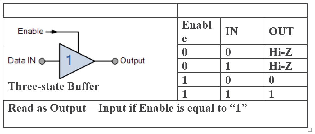
A active high Three-state Support like the 74LS241 octal cradle, is enacted when a rationale level “1” is applied to its “empower” control line and the information goes through from its contribution to its yield. At the point when the empower control line is at logic level “0”, the buffer output is impaired and a high impedance condition, Howdy Z is available on the output.
A active high three-state buffer can have a reversing output just as its high impedance state making a active high three-state modifying cradle as displayed.
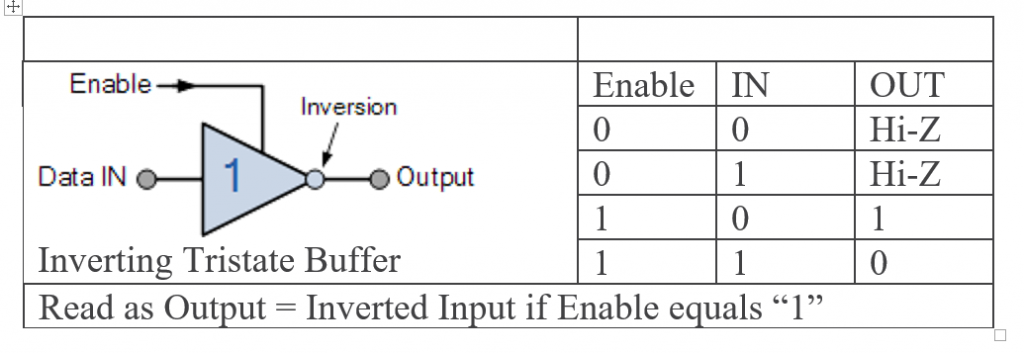
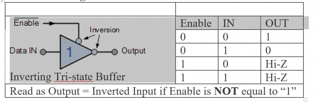
The output of an active-high inverting three-state buffer, such as the 74LS240 octal buffer, is activated when a logic level “1” is applied to its “enable” control line. The data at the input is passes through to the output but is inverted producing a complement of the input. When the enable line is LOW at logic level “0”, the buffer output is disabled and at a high impedance condition, Hi-Z.
The same two three-state buffers can also be implemented with an active-low enable input as shown.
Active “LOW” Three-state Buffer
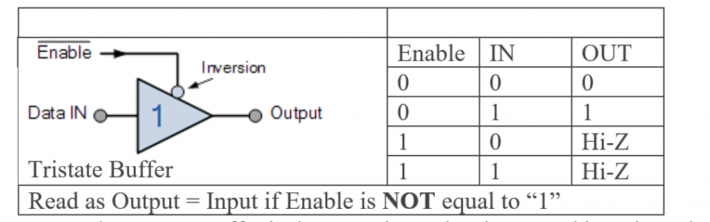
An Active-low Three-state Buffer is the opposite to the above, and is activated when a logic level “0” is applied to its “enable” control line. The data passes through from its input to its output. When the enable control line is at logic level “1”, the buffer output is disabled and a high impedance condition, Hi-Z is present on the output.
Active “LOW” Inverting Three-state Buffer
An Active low Three-state buffer is the inverse to the abovementioned, and is initiated when a logic level “0” is applied to its “empower” control line. The information goes through from its contribution to its output. At the point when the empower control line is at logic level “1”, the buffer output is disabled and a high impedance condition, Hi- Z is available on the output.
Three-state Buffer Control
We have seen over that a support can give voltage or current amplification inside .a computerized circuit and it can likewise be utilized to rearrange the info signal. We have additionally seen that advanced buffers are accessible in the tri-state structure that permits the yield to be successfully turned off creating a high impedance state (Hi-Z) comparable to an open circuit.
The Three-state Support is utilized in numerous electronic and microchip circuits as they permit different logic gadgets to be associated with a similar wire or transport without harm or loss of information. For instance, assume we have an information line or information transport with some memory, peripherals, I/O or a central processor associated with it. Every one of these gadgets is fit for sending or getting information to one another onto this single information transport simultaneously making what is known as a dispute.
Dispute happens when numerous gadgets are associated together in light of the fact that some need to drive their output high and some low. In the event that these gadgets begin to send or get information simultaneously a short out may happen when one gadget outputs to the transport a logic “1”, the inventory voltage, while one more is set at logic level “0” or ground, bringing about a short out condition and perhaps harm to the gadgets just as loss of information.
Computerized data is sent over these information transports or information thruways either sequentially, the slightest bit at a time, or it might be up to (at least eight) wires together in an equal structure, for example, in a microchip information transport permitting various three-state supports to be associated with similar information roadway without harm or loss of information as displayed.
Then, at that point, the Three-state buffer can be utilized to separate gadgets and circuits from the information transport and each other. On the off chance that the outputs of a few Three-state buffers are electrically associated together Decoders are utilized to permit just one bunch of Three-state buffers to be dynamic at any one time while different gadgets are in their high impedance state. An illustration of Three-state buffers associated with a 4-wire information transport is displayed beneath.
Three-state Buffer Control
Also read here for more topics