Introduction to Common Collector Amplifier
Common Collector Amplifier is also known as emitter-follower. Since the output voltages are in phase with the input signal and the magnitude is almost same as the input. Common Collector amplifier has the characteristics of high input resistance and it provides unity voltage gain approximately (AV=1). It only provides the current gain which is the ratio of output current (Ie) and the input current (Ib). The term common collector is used since the collector terminal is at ac ground since we replace all the voltage sources with ground while performing the ac analysis.
How to Evaluate the Voltage Gain of Common Collector Amplifier?
In order to evaluate the voltage gain of common collector amplifier, first we will draw the ac equivalent model of common collector amplifier which is shown in the figure below.
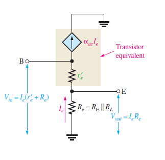
As we know that the voltage gain is the ratio of output voltages divided by the input voltages AV=Vout/Vin. Here Vout=Ve=IeRe and Vin=Ie(Re+re).
So,
AV= Ie Re /Ie(Re+re)
AV=Re /(Re+re)
if Re>re
then AV=Re /Re=1
Hence it is proved that the voltage gain of common collector amplifier is approximately equal to 1.
Why the Name Emitter Follower is Given?
Since the output voltage is at the emitter, it is in phase with the base voltage, so there is no inversion from input to output. Because there is no inversion and because the voltage gain is approximately 1, the output voltage closely follows the input voltage in both phase and amplitude; thus the term emitter-follower.
Current gain of Common Collector Amplifier
Common collector amplifier provides the current gain equal to the ration of emitter current (output current) and the base current (input current).
Ai=Ie/Ib=Ve/Re
Since Av=Ve/Vb= Ve= Av Vb
Ai=Av Vb/ Re
Common Collector Input Impedance
Although the common collector amplifier is not very good at being a voltage amplifier, because as we have seen, its small signal voltage gain is approximately equal to one (AV ≅ 1), it does however make a very good voltage buffer circuit due to its high input (ZIN) and low output (ZOUT) impedances, providing isolation between an input signal source from a load impedance load.
Another useful feature of the common collector amplifier is that it provides current gain (Ai) as long as it is conducting. That is it can pass a large current flowing from the collector to the emitter, in response to a small change to its base current, IB. Remember that this DC current only sees RE as there is no RC. Then the DC current is simply: VCC/RE which can be large if RE is small.
Common Collector Amplifier Example
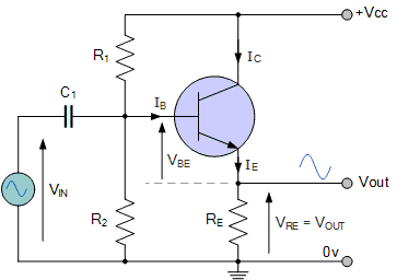
A common collector amplifier is constructed using an NPN bipolar transistor and a voltage divider biasing network. If R1 = 5k6Ω, R2 = 6k8Ω and the supply voltage is 12 volts. Calculate the values of: VB, VC and VE, the emitter current IE, the internal emitter resistance r’e and the amplifiers voltage gain AV when a load resistance of 4k7Ω is used. Also draw the final circuit and corresponding characteristics curve with load line.
Collector voltage, VC. As there is no collector load resistance, the transistors collector terminal is connected directly to the DC supply rail, so VC = VCC = 12 volts.
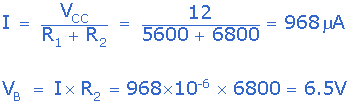
Emitter biasing voltage, VE
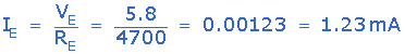
Emitter Current, IE
AC Emitter Resistance, r’e
![]()
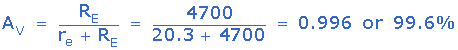
Voltage gain, AV
Also read here: