Design a project of road safety system
Design a project of road safety system. Our main goal is to create a Road Safety System. This system will warn the pedestrians of any incoming danger by playing an alarm tone, while they are crossing the road.
For this purpose, our circuit consists of two main parts. One part that transmits the infrared radiations, which are given off by the light emitting diode (LED). The other part receives the radiations, consisting of a photodiode and the circuitry that contains a speaker and other components to activate the speaker.
Normally, when the circuit is supplied external voltage. The transmitter transmits the IR radiations and the receiver receives it, not activating the circuit connected with it. Thus no sound is heard. But when there is any interruption in the way of IR radiations, the receiver activates the connected circuit and an alarm tone is played as a warning sign.
Our system works when the signal is red and pedestrians are crossing the roads. If any car will try to move across the zebra crossing, the system will detect an interruption in the way of IR radiations and then the receiver circuit would be activated. An alarm tone will be played to warn the pedestrians, which are crossing the roads. Design a project of road safety system
COMPONENTS:
The components that are used while making the system, are defined shortly ahead. The components are:
- Resistor
- Variable Resistor (Potentiometer)
- Capacitor
- Transistor
- Light Emitting Diodes (LED)
- Relay
- Printed Circuit Board (PCB)
- Photodiode
- LM555 Timer Chip
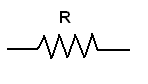
RESISTOR:
A resistor is a passive component that opposes the flow of current through it and the resistance is measure of component’s opposition to the current flow. The basic unit of measurement of resistance of a resistor is ohm. The symbol used for resistor is shown in the figure.
Based on the resistance type or the fabrication technique, the resistor can be classified as:
- Carbon Composition Resistors in which the resistance element is a slug of a resistive material (carbon in this case).
- Film Resistors in which the resistive element is a relatively thin layer of resistive material painted or deposited on a ceramic or a glass tube. The resistive material is carbon in case of widely popular Carbon Film Resistors.
- Wirewound Resistors in which the resistive element is a length of wire wound in one or more than one layer on an insulating core.
We can find the value of resistance simply by using ohms law i.e.
V = IR
Where, V is the voltage across the resistor
I is the current passing through it
And R is the resistance of the resistor
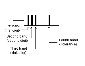
Another way of finding the resistance is to use the method of colour coding. Carbon composition, Semi-precision and Wirewound resistors are colour coded by three or four bands indicating their resistance value and another colour band indicating the tolerance. The first three or four bands give the resistance value and another band the tolerance. Width of the first band often indicates the type of the resistor. A first band wider than the other band indicates a wire wound resistor. Colours are given specified number.
- The first colour of the first band represents the significant digit of the resistance value.
- The second colour of the first band represents the second significant number of the resistance.
- The third colour of the first band specifies the number of zeros to follow.
- The colour of second band represents the tolerance of the resistor.
The figure below shows the colour coding of a resistor.
The table below shows the number which are assigned to the colours.
| Colour | Digit | Multiplier | Tolerance |
| Black | 0 | 1 | — |
| Brown | 1 | 10 | — |
| Red | 2 | 100 | — |
| Orange | 3 | 1000 | — |
| Yellow | 4 | 10000 | — |
| Green | 5 | 100000 | — |
| Blue | 6 | 1000000 | — |
| Violet | 7 | 10000000 | — |
| Grey | 8 | — | — |
| White | 9 | — | — |
| Gold | — | 0.1 | ± 5% |
| Silver | — | — | ± 10% |
| No colour | — | — | ± 20% |
VARIABLE RESISTORS (Potentiometer):
The resistance value of variable resistors can be varied over the specified resistance range. Variable resistors can be classified as:
- Potentiometers
- Rheostats
- Trimmers (Presets)
Construction:
All the three types of variable resistors have the same construction but differ in the way they are connected and hence performing different jobs.
All the three types are three terminal resistors with two fixed terminals and a third terminal (wiper) that is attached to a moveable tap that can be moved along the length of the resistive element thus varying the resistance between the movable terminal and the fixed terminal. These three types are simply and collectively known as potentiometers.
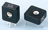
Construction of a flat semi-circular graphite potentiometer with a sliding contact (wiper) is shown in the figure. The wiper is connected through another sliding contact to the third terminal. On panel pots, the wiper is usually the central terminal. For single turn pots, this wiper typically travels just under one revolution around the contact. ‘Multiturn’ potentiometers also exist, where the resistor element may be helical and the wiper may move 10, 20, or more complete revolutions. Besides graphite, other materials may be used to make the resistive element. These may be resistance wire, or carbon particles in plastic, or a ceramic/metal mixture called cermet.
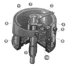
Construction of a wire-wound circular potentiometer. The resistive element (1) of the shown device is trapezoidal, giving a non-linear relationship between resistance and turn angle. The wiper (3) rotates with the axis (4), providing the changeable resistance between the wiper contact (6) and the fixed contacts (5) and (9). The vertical position of the axis is fixed in the body (2) with the ring (7) (below) and the bolt (8) (above).
· Potentiometer:
Variable resistors used as potentiometers have all three terminals connected. This arrangement is normally used to vary voltage, for example to set the switching point of a circuit with a sensor, or control the volume (loudness) in an amplifier circuit. If the terminals at the ends of the track are connected across the power supply then the wiper terminal will provide a voltage which can be varied from zero up to the maximum of the supply. Symbol used for the potentiometer is shown in the figure.

- Rheostats:
A rheostat is a two-terminal variable resistor. Often these are designed to handle much higher voltage and current. Any three-terminal potentiometer can be used as a two-terminal variable resistor, by not connecting to the 3rd terminal. Two terminals are used one connected to an end of the track, the other to the moveable wiper. Turning the spindle changes the resistance between the two terminals from zero up to the maximum resistance.
Rheostats are often used to vary current, for example to control the brightness of a lamp or the rate at which a capacitor charges. Symbol used for rheostat is shown in the figure.

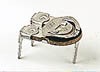
- Trimmers (Presets):
These are miniature versions of the standard variable resistor. They are designed to be mounted directly onto the circuit board and adjusted only when the circuit is built. For example to set the frequency of an alarm tone or the sensitivity of a light-sensitive circuit a small screwdriver or similar tool is required to adjust presets. Presets are much cheaper than standard variable resistors. Symbol used for trimmer is shown in the figure.
Multiturn presets are used where very precise adjustments must be made. The screw must be turned many times (10+) to move the slider from one end of the track to the other, giving very fine control. Figure below shows two types of presets.

CAPACITOR:
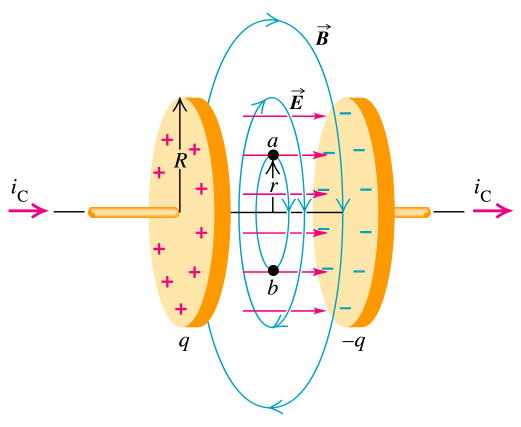
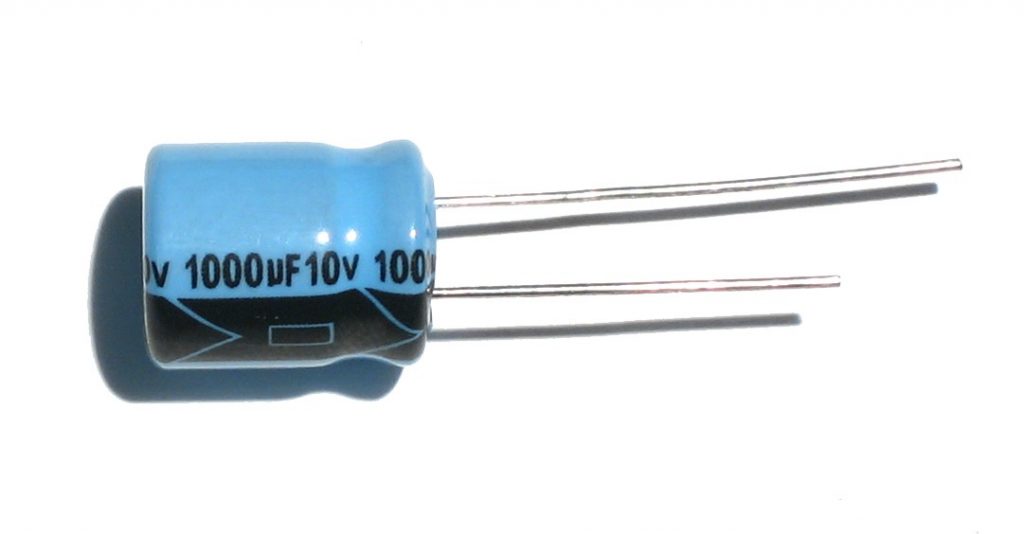
A capacitor is an electrical/electronic device that can store energy in the electric field between a pair of conductors (called “plates”).
A capacitor consists of two conductive electrodes, or plates, separated by a dielectric. Capacitors are often used in electrical circuits as energy-storage devices. They can also be used to differentiate between high-frequency and low frequency signals. This property makes them useful in electronic filters.
The capacitor’s capacitance (C) is a measure of the amount of charge (Q) stored on each plate for a given potential difference or voltage (V) which appears between the plates:
Q = CV
Where, Q is the charge stored
C is the capacitance
And V is the voltage applied across the electrodes
Capacitance:
The capacitor’s capacitance (C) is a measure of the amount of charge (Q) stored on each plate for a given potential difference or voltage (V) which appears between the plates:
Q = CV
Where, Q is the charge stored
C is the capacitance
And V is the voltage applied across the electrodes
Charging and Discharging of a Capacitor:
When a capacitor is connected to a DC voltage source then a steady current through a capacitor deposits electrons on one plate and removes the same quantity of electrons from the other plate. This process is commonly called ‘charging’ the capacitor.
Now if any load is connected across this charged capacitor then it will discharge through this load. The charging and discharging time of a capacitor is determined by the time constant which is determined by the following formula
T=R.C
Where ‘R’ is the resistance of load and C is the capacitance of the capacitor.
Stored Energy:
As opposite charges accumulate on the plates of a capacitor due to the separation of charge, a voltage develops across the capacitor due to the electric field of these charges. Ever-increasing work must be done against this ever-increasing electric field as more charge is separated. The energy (measured in joules, in SI) stored in a capacitor is equal to the amount of work required to establish the voltage across the capacitor, and therefore the electric field. The energy stored is given by:
U = (1/2) CV2 = (1/2) Q2/C = (1/2) VQ
Where, V is the voltage across the capacitor.
Applications:
- Reservoir capacitors are used in power supplies where they smooth the output of a full or half wave rectifier.
- They are often used to separate the AC and DC components of a signal. This method is known as AC coupling or “capacitive coupling”
- Capacitor is used to decouple one part of a circuit from another. Noise caused by other circuit elements is shunted through the capacitor reducing the effect they have on the rest of the circuit. It is most commonly used between the power supply and ground.
TRANSISTOR:
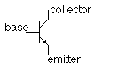
A transistor is a semiconductor device, commonly used to amplify or switch electronic signals. The transistor is the fundamental building block of computers, cellular phones, and all other modern electronic devices. The symbol used for transistor is shown in the figure.
Transistors are composed of three parts:
- A Base
- A Collector
|
- An Emitter
One of the outside layers is called the emitter, and the other is known as the collector. The middle layer is the base. The places where the emitter joins the base and the base joins the collector are called junctions.
Emitter: The emitter region is heavily doped as compared to the other two regions and thickest among all.
Base: The base is the gate controller device for the larger electrical supply. Base is very lightly doped region and thin as compared to the other two regions.
Collector: The collector region is normally doped and thicker as compared to the base but a little thinner as compared to emitter.
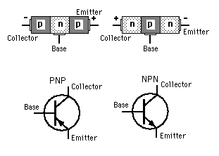
Structure:
A transistor consists of a thin piece of one type of semiconductor material between two thicker layers of the opposite type (also called junction transistor).
If the middle layer is p-type, the outside layers must be n-type. Such a transistor is an NPN transistor.
If the middle layer is n-type and the outer layers are p-type, such a transistor is called PNP transistor. The symbols are shown in the figure.
The layers of a transistor must have the proper voltage connected across them. The voltage of the base must be more positive than that of the emitter. The voltage of the collector, in turn, must be more positive than that of the base. The voltages are supplied by a battery or some other source of direct current. The emitter supplies electrons. The base pulls these electrons from the emitter because it has a more positive voltage than does the emitter. This movement of electrons creates a flow of electricity through the transistor.
The current passes from the emitter to the collector through the base. Changes in the voltage connected to the base modify the flow of the current by changing the number of electrons in the base. In this way, small changes in the base voltage can cause large changes in the current flowing out of the collector.
Applications:
By changing the biased voltages transistor can be used in a circuit for different purposes e.g.
- It can act as an amplifier when the emitter-base junction is forward biased and collector-base junction is reverse biased.
- It acts like a switch when the emitter-base and collector-base junctions are reversed biased.
For complete report, click here