Design a project of hurdle detection vehicle
Design a project of hurdle detection vehicle. To provide a safety system in vehicles, our project plays an important role. Implementation of our project in automobiles ensures their safety from the obstacle ahead.
Along with some amendments, this project can also be implemented in industries where moving objects are desired to remain at a specific distance.
Our project “HURDLE DETECTION VEHICLE,” works by transmitting short pulses of ultrasonic sound waves. The ultrasonic sensor will receive reflected signal from the hurdle and send interrupt to controller, for taking appropriate action. The microcontroller calculates the distance from the hurdle. If the calculated result is less than the specific distance, then the DC motor will stop to avoid collision. The microcontroller used for the said purpose is 40 pin PIC 16F877.
Summary
As the auto-mobility invented many accidents used to occur due to the negligence and sometimes unconsciousness of the driver. “HURDLE DETECTION VEHICLE,” will sense the hurdle and the vehicle will stop at once.
The project uses standard transducers to receive and transmit the ultrasound and a comparator to set the threshold echo detection. The ultrasonic transducers are standard 40 kHz type. The time from transmission of the pulse to reception of the echo is the time taken for the sound energy to travel through the air to the object and back again. The 40 kHz signal is easily generated by the microcontroller but detection requires a sensitive amplifier. This is followed by a peak detector and comparator which set the sensitivity threshold so that false reflections (weaker signals) are ignored.
If a signal is received, an interrupt is generated. The interrupt routine is only enabled when required and when the capture occurs (if it does) only the first capture is stored – so that later reflections are ignored.
If an interrupt occurs microcontroller will stop the normally running dc motor, thus causing a brake.
Purpose
This project can reduce collisions by identifying obstructions in front of the vehicle, by automatically applying brakes when needed.
It can also be used to ensure a safe distance between a vehicle and all vehicles within defined vicinity. On the basis of distance, the vehicles would be able to communicate with each other, exchanging data on speed, orientation, perhaps even on driver awareness and intent. This could increase safety for nearby vehicles, while enhancing the overall sensitivity of the system, for example, by performing an automated emergency maneuver (braking) more effectively.
- With some modifications in the system, this can be used in industrial automated systems.
- Other sensing systems such as speed measuring, or environment monitoring can be added to the present system to make it more effective for vehicle safety
Hardware Components
2.1. PIC 16F877
2.2. MAX232
2.3. Tuned Circuits
2.4. Transducer
2.6. Relay
2.7. Motor
2.8. LM311
2.9. Voltage Regulator
Hardware Design
- System Level Design
- Transmitter Circuit Operation
- Receiver Circuit Operation
- Motor Circuit Operation
- Design Strategies
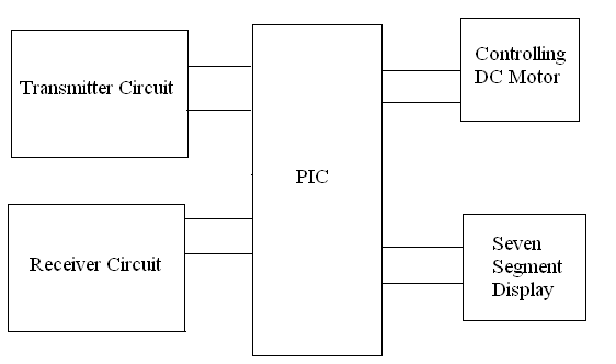
System Level Design
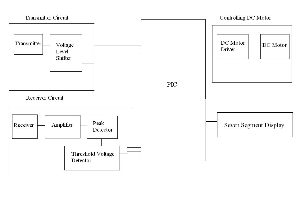
The system level design approach is shown in the below diagram. The transmitter circuit transmits short pulses after the small time. If there is any hurdle present, the echo is reflected back from it and it is received by the receiver. On receiving echo, the receiver circuit is activated and generates an interrupt for the microcontroller. Then the microcontroller stops its timer and from this value the distance is calculated. The calculated distance is then displayed on seven segments. If the calculated distance is less than the specified distance the vehicle is stopped to avoid collision.
Transmitter Circuit Operation
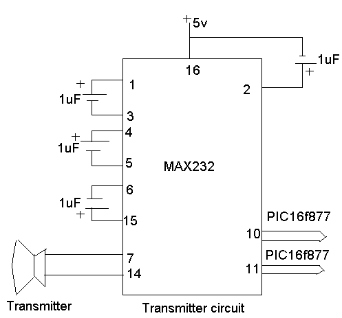
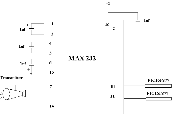
Here MAX232 is used as level converter and acts as a buffer driver. It includes two transmitter and two receivers .Its two receivers accepts two square waves of opposite polarities from microcontroller and convert them to 10v and -10v. It requires 4 external capacitors as shown in the diagram. These are used by the internal charge pump to create +10 volts and -10 volts. The output from its receivers is connected to the ultrasonic transmitter. So more power is delivered to the transmitter due to which it transmits a stronger signal.
Receiver Circuit Operation
The circuit diagram of receiver side is shown below. On the receiver side, tuned amplifiers are used which amplify the small echo signals of 40 kHz bandwidth and reject the signal outside this band.
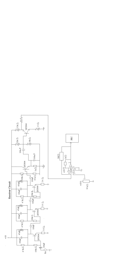
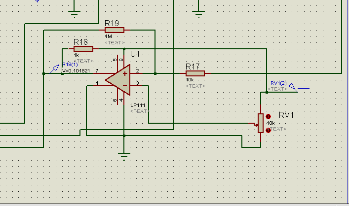
This makes system less sensitive to noise. The gain of these amplifiers is quite large. After amplification, the signal is fed to the peak generator circuit which is actually a common emitter amplifier. The next stage amplifies these peaks and saturates them. This signal is then fed to the comparator which is designed using LM311 comparator IC. The reference level is adjusted by the variable resistor on the comparator pin 3. As the signal exceeds the set reference level a square wave is generated which acts as interrupt for the microcontroller.
The tuned 40 KHz resonant frequency is calculated by the formula
fr=1/2π√LC
From the parallel resonant circuit we have
L=47µH
C=330nF
So,
fr = 1/2π√(47µH)( 330nF)
fr = 40.4KHz
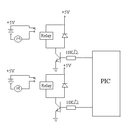
- Motor Circuit Operation
The circuit which is used for controlling motor is shown in the below diagram. The basic purpose of this circuit is just to start and stop the vehicle if the hurdle is very close to it. As it can be seen in the diagram, motor is not directly connected to microcontroller but it is controlled through relay. Since motor is a higher power device so relay is used for it. The transistor is used here to switch current up to 800mA. Note that the diode is used across the relay to suppress back emf. This is to prevent damage to the transistor when the relay switches off.
Design Strategies
Transmitter:
For the transmitter side we have two different circuits but the selection was made depending upon the salient features:
The first circuit that we selected for the transmitter is shown in figure below
The main flaw of this circuit was that we did not know the impedance of our ultrasonic transducers, so the value of the inductor could not be determined to transfer the maximum power through the transmitter.
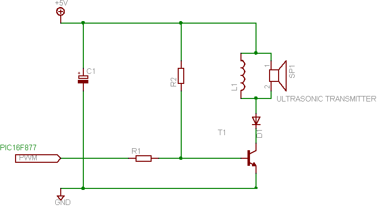
Due to this drawback, following circuit is selected as shown in figure below
The above circuit gives the transmitter voltage, shifted signal to transmitter from controller. This increased voltage level will strengthen the transmitted signal.
Receiver:
Similarly for the receiver side we have two circuits. The first one is shown in figure below
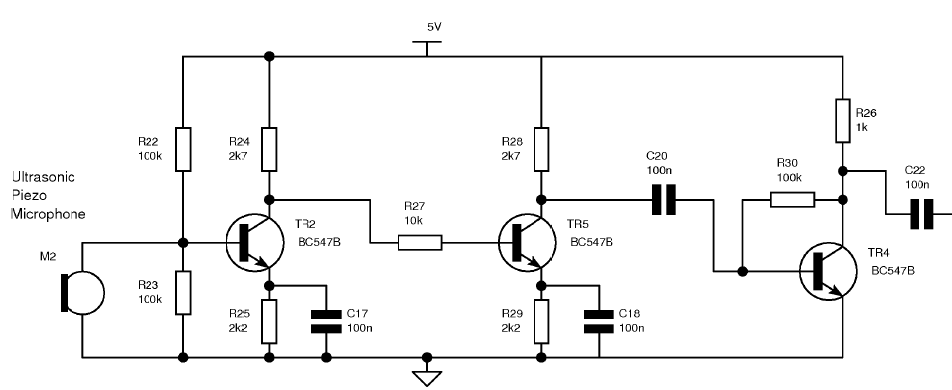
The flaw of this circuit was that it amplifies the signal of all the frequencies but not a particular frequency signal. Also the input signal of small values e.g., 10mV can not be amplified by it. That’s why tuned amplifier circuit is selected which amplifies the signal in the particular range of frequencies. It
can also amplify the signal of smaller values. The circuit diagram of the tuned amplifier is shown in given figure

Simulation Results
5.1. Transmitter Simulation
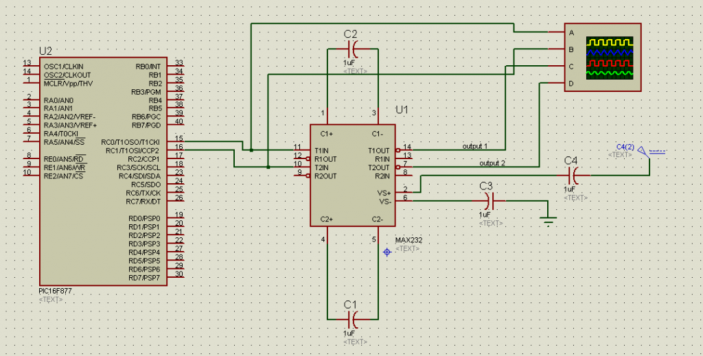
Fig 5.1.1 shows the transmitter circuit, which comprises of transmitting sensor, max232 and 16F877 PIC controller. The controller generates two out of phase, 40 kHz square pulses at pins 15 and 16 (which are C0 and C1). The pulses generated by the controller are 5V in magnitude. The max232 shifts the level up to approximately +8.5 to -8.5 V. these signals are given to the transmitter, produces ultrasonic waves of 40 kHz.
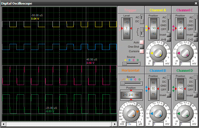
Fig 5.1.2 shows the simulation results. Pin 14 and 7 of max 232 gives the level shifted output waveform. First two signals are output from controller and input to max 232. The last two signals are the output of max232 and would be feed into the transmitter.
Receiver Simulation
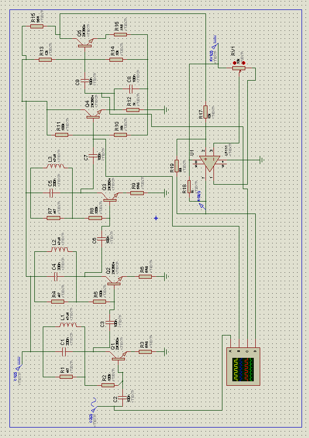
Fig 5.2.1 shows the complete receiver circuit. The receiver circuit can be divided into three main parts. The first is 3-stage tuned amplifier, second is peak detector and third is a comparator
Above figure shows the output of every stage of the tuned amplifier. The first signal is input signal. The following waveforms are the output of every next stage of tuned amplifier.
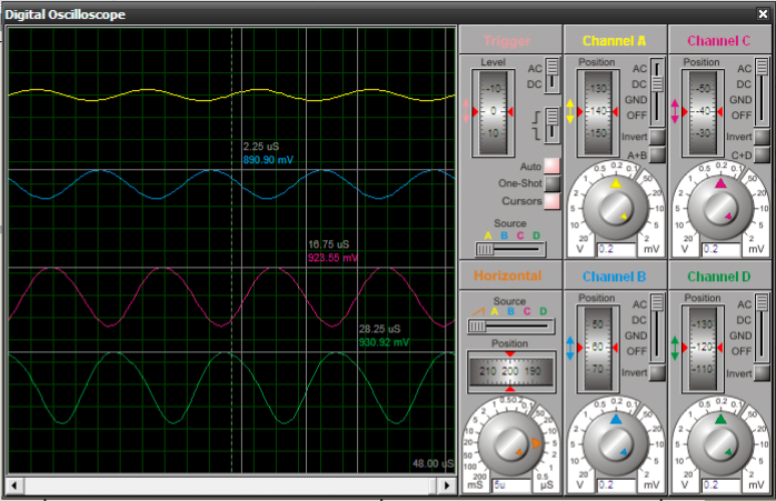
Fig above shows the output of receiver circuit, when the signal is received at the receiver. The first waveform is the received signal. The second is the amplified waveform from the tuned circuit. The next waveform shows the output of peak detector and the last one shows the output of comparator. These pulses causes interrupt event to occur at the controller.
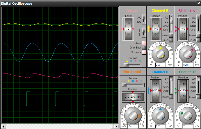
When the signal is not received by the receiver, the output of comparator is zero. Hence, no interrupt event would occur.
Also read here
https://eevibes.com/electronics/design-a-project-of-road-safety-system/