Abstract
Soft-starting and speed control of three phase induction motor project. The purpose of Soft-starting and speed control of three phase induction motor and its protection is to design a prototype which can manipulate the voltage and current values accurate into motor without any initial jerk or torque which can be dangerous. Although controlling speed of three phases induction motor is a challenged phenomenon but with help of some basic configurations of inverters, converters and filters, this milestone can be achieved. The soft starting gives a longer life to motor. The speed control feature gives the user command over the device to control motor accordingly. The basic protection of motor is included in terms of LED’s and LCD display for speed control.
The main theme of our project is to use the pulses fed to PIC controller to perform the required action. The width of pulses determines the initial soft start for motor and its speed. The fast flowing pulses triggers the gate triggering IC which in turn operates the MOSFETs. Hence initial soft starting and the speed control for three phase induction motor is achieved. Soft-starting and speed control of three phase induction motor project.
Likewise the hardware implementation, the software implementation our circuit is achieved with help of PROTEUS. The basic simulation is done on the PROTEUS to configure the circuit and its functionality. It is then implemented on hardware accordingly.
What is the induction motor?
Induction motor is the most widely used motor in industry. It is used in a number of applications such as fans, blowers, crushers, grinders, mixers, pumps, cranes, compressors, and many other modern industrial applications. When the motor starts it draws heavy current normally 7 to 10 times its rated current that is called inrush current: this current causes a number of problems to the system containing the motor.
Induction motors especially squirrel cage type make up a large part of the load industrial applications due to their simplicity of construction, economical matter, reliability and relatively high efficiency. Starting motors at full voltage, referred to as across- the line or direct on line (DOL) results increased mechanical wear through rapid acceleration and very high currents causing considerable stresses on supply. By using soft starter, in many applications, smooth acceleration with reduced stress on the mechanical drive system and reduction of inrush current can be achieved. Therefore eliminating voltage dip and brown out conditions could be avoided . Soft-starting and speed control of three phase induction motor project.
Soft Starters allow the machine to start by adjusting the induction motor terminal voltage, thereby reducing the voltage to each phase of a motor and gradually increasing the voltage until the motors gets up to full voltage/speed all at a fixed frequency.
The profile of voltage increasing depends on the control scheme .The most prevalent type of the soft starters which will be focused in this project comprises three TRIACs. The ac voltage of the motor is reduced and controlled by varying the firing angle (α) of the TRIACs . The methods to calculate the firing angle (α) of the TRIACs can be categorized as two groups: open loop and closed loop control.
In open loop methods a start voltage profile is produced independent of the current drawn, or the speed of the motor. The most common closed loop starters are referred to as current controlled soft starter in which the current drawn by the motor during start is monitored and could dynamically modify the voltage profile to reach the desired response.
Methodology
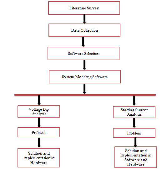
1.2.1 Data Collection
Actual data is collected from the industrial facilities and from experiments related to motor starting.
1.2.2. Software Selection
After data collection, some software was required for simulations, Keil u vision4 software is selected for PIC 16f877 microcontroller programming and Proteus software is selected for simulation of complete circuit. It provides much flexibility and close to real environment for the user. The collected data is modelled in software.
1.2.3. Simulation and Implementation
Problem is identified and solution is developed in the form of soft-starter. Performance of the three phase induction motor is checked again after the inclusion of soft-starter. Simulation and practical results show that the efficiency of the motor and power system can be increased using soft starter.
1.3 Three Phase Induction Motor
1.3.1 Motors
Modern electrical motors are available in many different forms, such as single phase motors, three phase motors, synchronous motors, asynchronous motors, brake motors, brushless motors, and so on. They all have their own performance and characteristics.
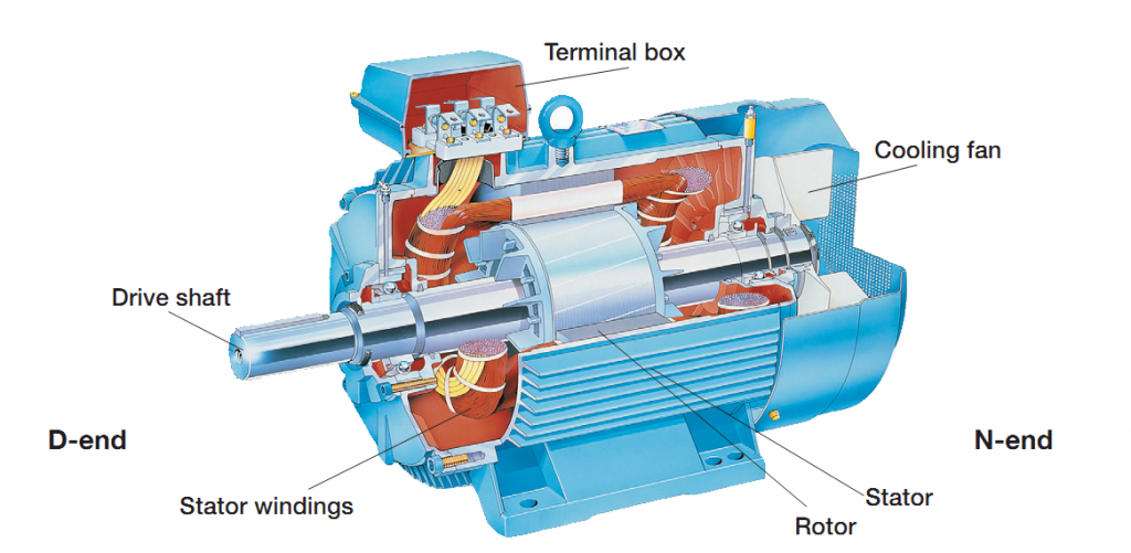
To ensure a long life for motor it is important to keep it with a correct degree of protection, under heavy-duty condition in a severe environment and satisfy the power quality given to the motor. The end of the motor is defined in the IEC-Standard as D-end and N-end: The D-end is normally the driven end of the motor. The N-end is normally the non-driven end of the motor.
1.3.2 Three Phase Induction Motor
Like any of electric motors, a 3-phase induction motor has a stator and a rotor. The stator carries a 3-phase winding (called stator winding) while the rotor carries a short-circuited winding (called rotor winding). Only the stator winding is fed from 3-phase supply. The rotor winding derives its voltage and power from the externally energized stator winding through electromagnetic induction. The induction motor may be considered to be a transformer with a rotating secondary and it can, therefore, be described as a “transformer-type” A.C. machine in which electrical energy is converted into mechanical energy
The three-phase induction motors are the most widely used motors in industry. They run at essentially constant speed from no-load to full-load. However, the speed is frequency dependent and consequently these motors are not easily adapted to speed control. Therefore we usually prefer D.C motors when large speed variation is required. Nevertheless, the 3-phase induction motors are simple, rugged, low priced, easy to maintain and can be manufactured with characteristics to suit most industrial requirements [12].
1.3.2.1 Advantages
1) It has simple and rugged construction.
2) it is relatively inexpensive.
3) It requires less maintenance.
4) It has high efficiency and reasonably good power factor.
5) It has self-starting torque.
1.3.2.2 Disadvantages
1) Its speed regulation is not easy.
2) Its starting torque is inferior to D.C shunt motor.
1.3.3 Principle Of Operation of induction motor
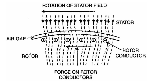
Consider a portion of 3-phase induction motor as shown in Fig 1.2. The operation of the motor can be explained as under:
When 3-phase stator winding is energized from a 3-phase supply, a rotating magnetic field is set up which rotates round the stator at synchronous speed Ns (= 120 f/P).The rotating field passes through the air gap and cuts the rotor conductors, which as yet, are stationary. Due to the relative speed between the rotating flux and the stationary rotor, E.M.F. is induced in the rotor conductors. Since the rotor circuit is short-circuited, currents start flowing in the rotor conductors. The current-carrying rotor conductors are placed in the magnetic field produced by the stator. Consequently, mechanical force acts on the rotor conductors. The sum of the mechanical forces on all the rotor conductors produces a torque which tends to move the rotor in the same direction as the rotating field.
The fact that rotor tends to follow the stator field (i.e., rotor moves in the direction of stator field) can be explained by Lenz’s law. According to this law, the direction of rotor currents will be such that they tend to oppose the cause producing them. Now, the cause producing the rotor currents is the relative speed between the rotating field and the stationary rotor conductors. Hence to reduce this relative speed, the rotor starts running in the same direction as that of stator field and tries to catch it. [12]
When motor is started, it has to provide sufficient torque to derive a load. For that purpose it draws high current. Another reason for high inrush current is the back E.M.F. At starting, back E.M.F is very low and it gradually increases until the motor reaches the full speed..
1.3.4 Equivalent Circuit Parameters Calculation For 3-phase induction Motor
After selection of the motor a series of tests are performed to calculate the equivalent circuit parameters of the motor.
1.3.4.1 Stator Resistance:
With the rotor at standstill, the stator phase resistance is measured by applying a dc voltage and the resulting current. While this procedure gives only the dc resistance at a certain temperature, the ac resistance has to be calculated by considering the wire size, the stator frequency and the operating temperature [12-13].
Also click below for complete report
final report of induction motor speed control
Also read here
https://eevibes.com/engineering-projects/unmanned-ground-vehicle/