what are the DC machines?
what are the DC machines? A DC motor is similar in construction to a DC generator. In fact, a DC generator will work like a motor when its field and armature coils are connected to a DC power source. The basic construction is the same, be it a generator or an engine. Principle of operation: The principle of operation of a DC motor can be established as when a conductor carrying current is placed in a magnetic field; Suffers a mechanical force. In a practical DC motor, the winding induces the required magnetic retention, while the armature conductor acts as a current conductor and the armature cables are subjected to a force.
When the conductors are placed in the peripheral grooves, the individual force experienced by the conductor acts as a torque or rotation force on the armature, called torque. The torque is the product of the force and the radius of action of this force, so the whole frame suffers a couple and begins to rotate. Consider a single conductor placed in a magnetic field, the magnetic field is produced by a permanent magnet, but in a DC motor, it is produced by the winding of the field when a current is being carried.
Now, this driver is excited by an independent power source to carry a current in a particular direction. Note that it carries a current of a current. Any current-carrying conductor produces its own magnetic field around it, so this conductor also generates its own flow around it. The direction of this flow can be determined by the rule of the right thumb. For the direction of the current considered, the direction of the flow around the conductor is in the sense of clockwise.
Two currents are present. 5. Flow produced by a permanent magnet called the main flow. 6. Flow produced by the conductor current driver. In the following figure, it is clear that, on one side of the controller, the two flows are in the same direction in this case, to the left of the controller, which collects the flow lines when two flows help each other. On the contrary, to the right of the driver, the two flows are in opposite directions and, therefore, try to cancel each other. As a result, the density of the flow lines in this area weakens. Then, to the left, there is a zone of high flux density, while to the right of the controller, there is a zone of low flux density, as shown. The distribution of the flow around the conductor is like a fluted connection stretched under tension.
It exerts a mechanical force on the impeller that acts from a zone of high density of flow to a zone of low density of flow, that is to say, from left to right in relation to the case considered, as indicated above. . In the practical DC motor, the permanent magnet is replaced by the field winding that produces the required flow winding, which produces the required flow called the main flow and all the cables of the armature are subjected to mechanical force at the periphery of the gram of armor. . As a result, the global reinforcement suffers a torsional force called torque and induces the state of the engine in rotation.
There are five main types of DC motors commonly used:
- DC motor excited separately
- DC bypass motor
- Permanent magnet DC motor
- DC series motor
- Composite direct current motor
Series Wound DC Motor or DC Series Motor
A serial coil DC motor, as in the case of a bypass coil DC motor or a composite coil DC motor, falls into the category of self-excited DC motors, and draws its name because the field winding it is connected here in series with the winding armature. Therefore, the field windings are exposed to the entire armature current, unlike the bypass motor.
Construction of Series DC Motor
In terms of construction, an engine is similar to all other types of DC motors in almost every respect. It includes all the fundamental components, such as the stator containing the field winding or the rotor that carries the armature cables, and the other vital elements, such as the commutator segments or the brush, all fixed in the proper order, as in the case of a generic DC motor.
However, if we look closely at the field and armature wiring of this DC motor, we will clearly distinguish it from other members of this type.
To understand this, let’s go back to the basic fact mentioned above, namely, that this motor has a field coil connected in series with the winding of the armature. For this reason, a relatively higher current flows through the field coils and is designed accordingly, as shown below.
- The field coils of the DC series motor are wound with relatively fewer turns because the current in the field is the armature current and, therefore, requires less than the required number of turns.
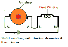
The cable is heavier because its diameter increases considerably to provide a minimum electrical resistance to the entire armature current flow.
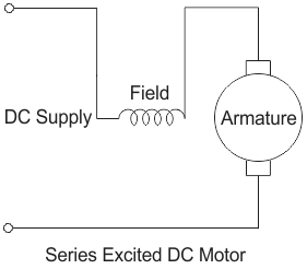
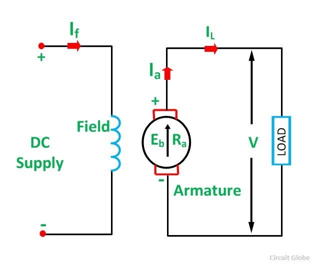
- Despite the differences mentioned above, the operation of this DC motor remains unchanged because the current in the field is reasonably high to produce a field strong enough to generate the required torque. To better understand this, consider the voltage and current equation of the DC series motor.
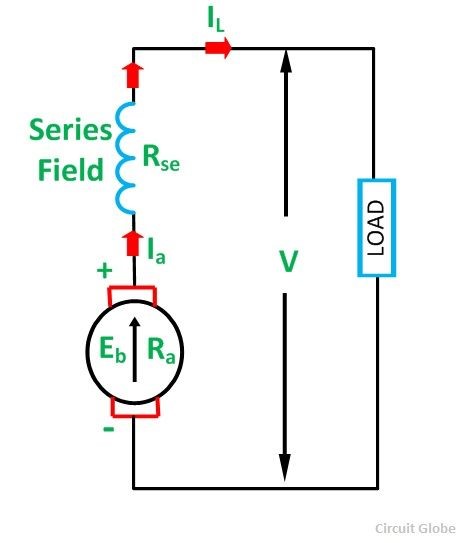
The following diagram shows the electrical configuration of a typical series DC coil motor.
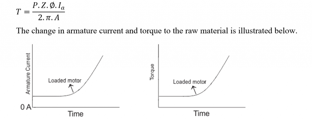
Speed and Torque of Series DC Motor
A series winding motor has a linear relationship between the field current and the amount of torque produced. that is, the torque is directly proportional to the current throughout the range of the graph. As in this case a relatively higher current flows in the field winding of heavy series with a thicker diameter, the electromagnetic torque produced here is much higher than normal. This high electromagnetic torque produces a motor speed strong enough to lift a heavy load and overcome its initial rest momentum. And for this reason in particular, the motor becomes extremely essential as a starting motor for most industrial applications dealing with heavy mechanical loads such as large cranes or large pieces of metal, etc. The motors of the series usually work for a very short time, only a few seconds. The goal is to start. Because if it runs for too long, the high series current will burn the field coils of the series, leaving the motor unusable.
Speed Regulation of Series Wound DC Motor
Contrary to what happens with a DC bypass motor, the motor of the DC series has a very poor speed control. that is, the series motor can not maintain its speed when it adds an external load to the shaft.
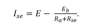
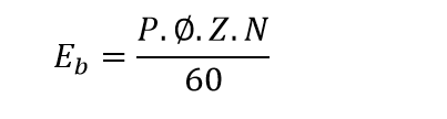
When a mechanical load is added to the shaft at any time, the speed automatically reduces the type of motor. But the term speed control refers to the motor’s ability to reduce the reduced speed to its original value in a reasonable time. But this motor is quite incapable of doing this because with the N speed reduction when adding the load, the back force factor given by
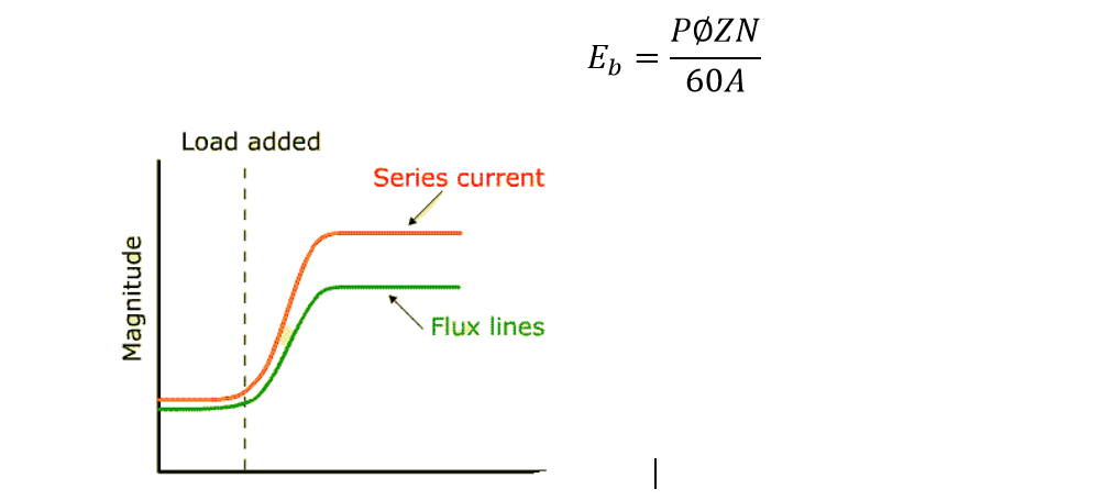
This reduction in the back-off effect Emf increases the net voltage E-Eb and, consequently, increases the field current in series.
The value of the current series in the field coil becomes so high that it tends to saturate the magnetic core of the field. As a result, the magnetic flux that connects the coils increases much more slowly than the increase in current beyond the saturation zone, as shown in the following figure.
Therefore, the low magnetic field produced does not provide the necessary force for the speed to return to its previous value before the application of the load.
Taking into account all the facts mentioned above, a DC coil motor in series is the most applicable as a starter for industrial applications.
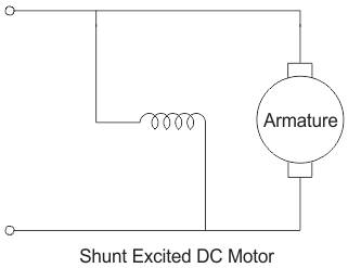
DC Shunt Motor:
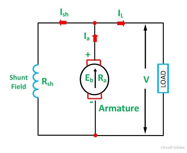
A DC shunt motor (otherwise called a shunt wound DC engine) is a kind of self-energized DC motor where the field windings are shunted to or are associated in parallel to the armature twisting of the engine. Since they are associated in parallel, the armature and field windings are presented to a similar supply voltage. In spite of the fact that there are discrete branches for the progression of armature current and field current – as appeared in the figure of underneath
Construction of a Shunt Wound DC Motor
The construction of a DC shunt motor is quite similar to that of other types of DC motor, as shown in the following figure.
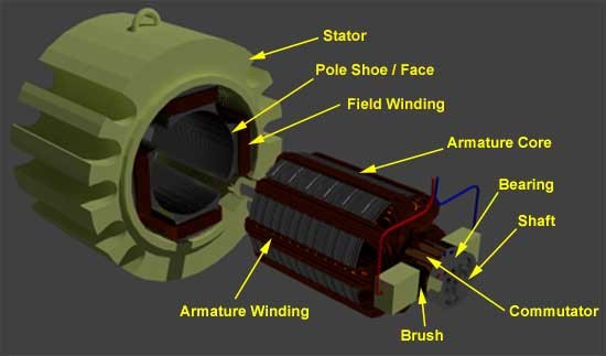
There is only one distinct feature in its design that can be explained by taking into account the torque generated by the motor. Produces high torque,
- The armature winding must be exposed to a much higher current than the inductive windings because the torque is proportional to the armature current.
- The field winding must be wound several times to increase the flow connection, since the flow connection between the field winding and the armature is also proportional to the torque.
Taking into account these two criteria mentioned above, a DC shunt motor has been designed so that the inductor coil has a much higher number of revolutions to increase the net flow link and a diameter of 50%. Lower conductor to increase the resistance to the armature winding of the DC motor. Therefore, a bypass direct current DC motor is visually distinguished, under static conditions, from the motor of the DC series (with coarser field coils) of the self-excited type of motor class.
Self-Speed Regulation of a Shunt Wound DC Motor
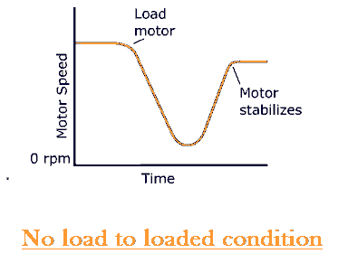
A very important and interesting fact about the DC shunt motor is its ability to self-regulate its speed when the load is applied to the shaft of the rotor terminal. Essentially, this means that when the operating state of the engine is switched from no load to loaded, it is surprising that there is no significant change in the speed of operation, as would be expected in the absence of changes in the speed regulation from the outside.
- Initially considering that the engine runs at idle or low load at a rotational speed per minute.
- When adding a load to the shaft, the motor initially slows down, but this is where the concept of self-regulation comes in.
- At the beginning of the load on a bypass DC motor, the speed drops sharply and, together with the speed, also reduces the rear force factor, Eb. From Ebα N, given by,
This can be graphically explained below.
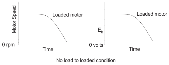
This reduction of the emf counter or the back emf Eb causes an increase in the net voltage. In net voltage Enet = E – Eb. Since the supply voltage E remains constant.
Due to this increase in net tension, the armature current increases and, therefore, the torque increases.
Since, Ia ∝ Τ given by
This increase in the amount of torque increases the speed and, therefore, compensates for the loss of speed of the load. Thus, the final speed characteristics of a DC motor.
From there, we can clearly understand this special ability of the DC shunt motor to adjust its speed by itself during charging and, therefore, correctly, the constant flow motor or the constant speed. Because of this, you find a generalized industrial application that requires a constant speed of operation.
what are the DC Generators?
Main Types of DC Generator
- Separately Excited
- Self-Excited
The DC generator converts electrical current into an electric current. The magnetic flux in a DC machine is produced by field coils carrying current. The current flowing in the windings induces a magnetic flux. This phenomenon is called excitement. The DC generator is classified according to the field excitation methods.
By excitation, the DC generators are classified as DC generators excited separately and in self-excited DC generators. There are also magnet-type DC generators. Self-excited DC generators are also classified as coil DC generators; DC series DC and coil generators. DC generators. Composite coil DC generators are divided into two: long derivation co-dc generators and short derivative dc generators.
The field pole of the DC generator is fixed and the armature cable rotates. The voltage generated in the armature cable is alternating in nature, and this voltage is converted to DC voltage in the brushes by means of the switch.
How many Types of DC Generators are here?
- Permanent Magnet Type DC Generator
- Separately Excited DC Generator
- Self-Excited DC Generator
- Shunt Wound Generator
- Series Wound Generator
- Compound Wound Generator
Permanent Magnet type DC Generator
In this type of DC generator, no field windings are placed around the poles. The field produced by the poles of these machines remains constant. Although these machines are very compact, they are only used in small sizes such as dynamos of motorcycles, etc. The main drawback of these machines is that the flow produced by the magnets deteriorates over time, which modifies the characteristics of the machine.
Separately Excited DC Generator
A DC generator whose winding or field coil is powered by an external or separate DC source is called a separately energized DC generator. The flux produced by the poles depends on the field current with the unsaturated region of the pole magnetic material. that is, the flux is directly proportional to the field current. But in the saturated region, the flux remains constant.
Self-Excited DC Generator
The self-excited DC generator is a device in which the current supplied by the field winding is supplied by the generator itself. In a self-excited DC generator, the field coils must be connected in parallel with the armature of the series or they can be connected partly and partly with the windings.
The self-excited DC Generator is further classified as
Shunt Wound Generator
In a shunt winding generator, the field winding is connected through the armature winding to form a parallel or shunt circuit. Therefore, a complete terminal voltage is applied through it. A very weak field current Ish crosses it because this winding comprises many turns of fine wire having a very high resistance Rsh of the order of 100 ohms.
Series Wound Generator
A coil generator in series the field coils are connected in series with the armature winding. The field winding in series transports the armature current. The series field winding consists of a few turns of coarse wire of larger section and low resistance, generally of the order of less than 1 ohm, because the reinforcing current has a very large value. Your convection diagram is shown below.
Characteristic of DC Generators – Separately Excited Self Excited Generator
The characteristic is the graph between the two dependent quantities. It shows the stable state characteristic of the DC generators. The characteristics of the DC generators explain the relationships between loads, excitation and voltage of the terminal by means of a graph. Here are the three important characteristics of a DC generator.
Magnetization Characteristic
This characteristic provides the variation of the generation voltage or the no-load voltage with the constant velocity field current. It is also called open circuit.
Internal Characteristic
The internal characteristic of the DC generator traces the curve between the voltage generated and the load current.
External Characteristics or Load Characteristics
The external or load characteristics provide the relationship between the voltage in the terminal and the load current at constant speed.
Contents:
- Characteristic of Separately Excited DC Generator
- Voltage Buildup in Self Excited Generator or Shunt DC Generator
- Voltage- Current Characteristic of Compound DC Generator
Characteristic of Separately Excited DC Generator
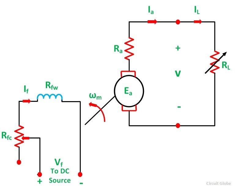
In a separately energized DC generator, a separate DC power supply is connected to the field winding. This source can be a battery, a diode rectifier, another DC generator or a controlled rectifier. The circuit diagram of a separately energized DC generator in the charged state is shown below.
For example a generator be driven at a constant speed by a prime mover. The field excitation (If) is adjusted to give rated voltage at no load. Throughout the operation, this value of voltage is kept constant. Let,
- Rfw is the resistance of the field winding
- Rfc is the resistance of the field rheostat to control the field current.
- Ra is the total resistance of the armature circuit, including the brush contact resistance.
- RL is the load resistance.
- IL is the load current
- Ea is the internal generated voltage
- V is the terminal voltage
- Ia is the armature current
The various equations for a separately excited DC generator are as follows
If there were no armature reaction, the generated voltage V0 would be constant as shown by a straight line (red color) in the figure below.
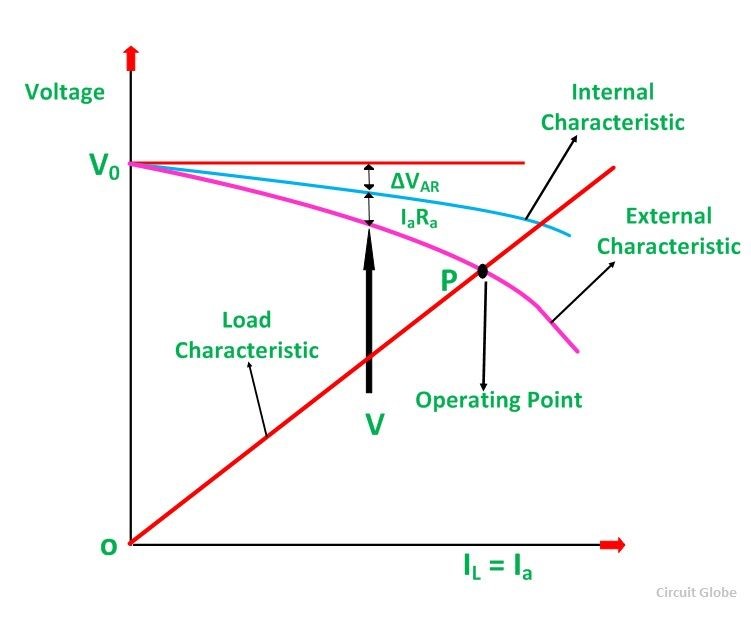
Characteristics of the terminals of a separately energized DC generator
There is a voltage drop of ΔVAR due to the reaction of the armature. The internal characteristic (Ea ~ IL) is also represented in the previous figure represented by a blue line. There is a voltage drop IaRa through the resistance of the armature Ra. The generator, external characteristic (V ~ IL) is also represented by the pink line.
The point P is called the operating point, which is the intersection of the generator, the external characteristic and the load characteristic given by the relation V = ILRL. This point P gives the operating values of the terminal voltage and the load current.
Voltage Buildup in Self Excited Generator or Shunt DC Generator
A self-excited generator is also known as the DC shunt generator because the field winding is connected in parallel to the armature. Therefore, the armature voltage provides the field current. This type of generator provides its own excitation field.
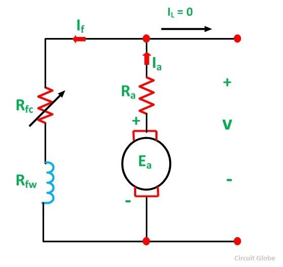
The equivalent circuit of a shunt DC Generator is shown in the figure below.
Bearing in mind the previous figure, suppose that the generator is empty and that the main motor drives the armature at a certain speed. This generator will accumulate the voltage in the desired terminal. The residual flow present at the field poles of the DC generator is responsible for the voltage increase. A small voltage ear is generated and is given by the following equation.
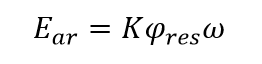
This voltage is of the order of 1 to 2 volts. This voltage circulates a current Si in the winding of the generator inductor. The field current is given by the equation.
I=V/R
The flux is increased by a magneto-motor force produced by the field current. As a result, the generated voltage Ea increases. This increase in armature voltage increases the voltage across the terminals. With the increase in voltage at the terminals, the field current Si increases again. This, in turn, increases the flow and, therefore, the tension of the armature increases further and the process of tension accumulation continue.
The voltage accumulation curve of a DC generator is shown below.
The generator is inactive during the tension process, so the following equations presented below provide a stable state operation.
Ia = If
V = Ea-Ia Ra = Ea-If Ra
Because the field current in a shunt generator is very small, the voltage drop of IfRa can be neglected. Then, the above equation becomes.
V = Ea
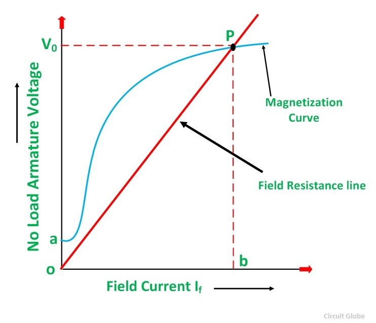
The straight line indicated by V = IfRf shown in the previous figure is called the field resistance line.
The voltage build-up in the DC shunt generator for several circuit resistors is shown below
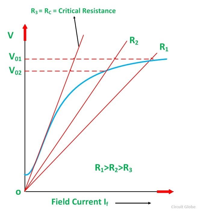
A decrease in the resistance of the field circuit reduces the slope of the field resistance line, resulting in a higher voltage. An increase in the resistance of the field circuit increases the slope of the field resistance line, resulting in a lower voltage. If the resistance of the field circuit increases to the critical resistance of the field (RC), the resistance line of the field becomes tangent to the initial part of the magnetization curve.
If the value of the field resistance is greater than the critical resistance of the field value, the generator fails to be excited. The curve below shows the variation of the no-load voltage with the fixed field resistance and the variable speed of the armature.
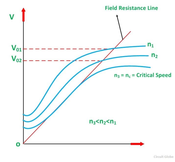
The magnetization curve varies with the speed and its ordinates for any field current are proportional to the speed of the generator. If the field resistance is kept constant and the speed is reduced, all points of the magnetization curve are reduced. At a particular speed, called critical velocity, the field resistance line becomes tangent to the magnetization curve. Below the critical speed, the voltage does not accumulate.
The following conditions must be met for voltage buildup in a self-excited DC generator.
There must be sufficient residual flow at the field poles.
The field terminals must be connected in such a way that the field current increases the flow in the direction of the residual flow.
The resistance of the field circuit must be less than the resistance of the critical field circuit.
If there is no residual flux at the field poles, disconnect the field from the armature circuit and apply DC voltage to the field winding. This process is called flashing the field.
Also read here about digital meters.