Remote Monitoring and Control of Environmental Variables via GSM
Remote Monitoring of Environmental Variables via GSM. Aim of this project is to make it possible for a remote user to remain in touch with what is happening at his home/office. To achieve this goal first we have selected two environmental variables to be monitored i.e. temperature and light. The system we have designed selects one of the two environmental variables to be sense continuously. After this temperature or light is monitored using sampling circuits and then if it goes above from a defined value, the user is then informed by SMS through GSM Network. Then from an appropriate response in the form of text message, appliance can be switched ON/OFF.
Introduction
In this project a remote place is selected to be monitored and controlled. Then some environmental variables (e.g. Temperature & light) are monitored continuously and information of that remote place is sent to the user via SMS using GSM network. When the user replies in a specific format using SMS, the information is processed and proper actions are taken. For example if temperature increases to a specified limit, by switching the air conditioner ‘ON’ the temperature is decreased or if temperature goes below a specific level the temperature will be increased by switching a heater ‘ON’. All actions are performed with the consent of the user. Similarly, if light intensity of that place goes below some certain threshold, the user is informed and lights are switched ‘ON’, if appropriate reply is received. All of the above communication between user and the remote area is done using GSM technology.
Purpose
Purpose of this project is to make it possible for a remote user to remain in touch with what is happening at his home/office. To achieve this goal first of all temperature/light intensity of remote place is monitored using sampling circuits and then information of high temperature or light is sent to the user, who replies to switch appliances on/off. For this purpose another circuit is designed.
Text messages can be received with the occurrence of an event automatically to GSM mobile (cell) phones. Command messages can be transmitted and switched the output-switch on/off remote equipment .SMS messages at occurrence of the certain events can be received- operation of entrance sensors. SMS messages can be sent for management of the various equipment’s (the conditioner, the heating equipment).
Our project can be used in warehouses where the refrigerators and freezers contain stock that has a significant value. By using our remote control module attached to the thermostat, the refrigeration company responsible for maintenance can be notified as soon as the temperature rises above a certain point. Once it is notified a technician can be dispatched to rectify the problem.
Project Overview
Our project “Remote Monitoring & Control of Environmental Variables via GSM” uses AT commands to inform remote user. When the user replies in a specific format using SMS, the information is processed and proper actions are taken.
- It solves the problem of manual monitoring
- Remote access is possible
- Device can also be controlled
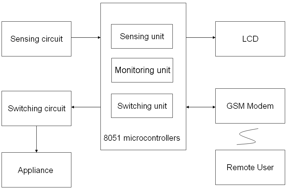
The basic system comprises of 4 elements:
- The remote unit itself together with the remote equipment to be monitored and controlled
- The GSM network message carrier service
- A mobile phone capable of GSM text messaging (SMS)
- The user(s)
Communication is by means of simple text messages in a special format that allows a high degree of security whilst allowing a flexible naming system for monitored and controlled functions.
Features
- Simple user interface i.e. uses standard text messages
- Low Power Consumption
- Almost unlimited range using GSM network
- 1 mobile phone can monitor and control many remote units
- Reduced man power
- Automatically sends alarm messages when go above threshold value
- Interrogate on demand functions
Scope
Global System for Mobile communication (GSM) has been one of the best trustable wireless communication system that can be accessed and used very easily. It is cost effective either if we consider the price of its transceiver module (a simple cellular phone) or the subscription fees. With the trend of huge growing usage of GSM during the past decade, network services are extended beyond speech communication to so many other custom specified applications, machine automation and machine-to-machine communication. This communication is implemented by using an AT command interfaced to a mobile phone. The user sends GSM data in the form of SMS (short message service) message to switch level above to below of any variable under consideration, like light, temperature etc.
The GSM network provides full duplex link to support the user requirement. The user can access the application remotely through SMS service where his message read and decoded by the micro controller attached to the mobile set through a suitable interface, usually data cable is used but also either Blue tooth or infrared links can be used.
Block Diagram
Hardware components used for designing the project
- Communicators & Cables
- Cell Phone Ericsson T68i
- Data Cable For Ericsson T68i
- Serial Port DB-9
- Sensors
- Temperature Sensor LM35
- Light Sensor LDR
- IC’s
- Micro Controller 8051
- Analog to Digital Convertor ADC0804
- MUX 4051
- TTL Logic Converter MAX232
- Relay 5V,12 Ampere, support 220V
- LCD 16X4
- Voltage Regulator 7805
- Battery 9 volts
- Resistors
- Variable resistor 10k
- Resistors 1k,470ohm,
- LED Color: Red(for Power indication)
- Diode 1N4007
- Capacitors 104,33pF
- Crystal Oscillator 0592 MHz
Communicators & Cables
Cell Phone (Ericsson T68i)
The Ericsson T68i is a compact mobile phone manufactured by the Ericsson company in 1999. It was the lightest and slimmest phone at the time, with a weight of only 81 grams unlike cell phones of the time (1999-2001) it had a fixed, stubby external antenna.

Ericsson T68i supports AT commands, so we use this cell phone to receive data from serial port and also to transmit it.
The T68i data cable
The T68i and data cable is used by a great number of people to unlock and flash (service cable) and to transfer files and phonebooks (data cable) on [Sony] Ericsson phones. The data cable utilizing four wires for GND, +5 (for cable circuit), Rx (Receive data) and Tx (Transmit data), three of which needs to be altered.
Ends of the data cable
The two ends of data cable are
-
- Phone connector
- Serial connector
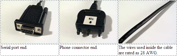
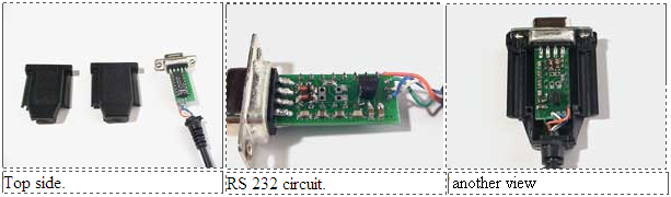
Phone Connector
The phone connector can easily be opened just by pressing the two tabs on the back end together and the front tabs apart and it easily flip open, here is the view of phone connector side of T68i data cable.
Serial Connector
All the conversion is done on this side, the connector is glued together with it, there is a RS 232 circuit embedded in a small chip and connected to the serial connector. Here is a view of serial connector side of T68i data cable
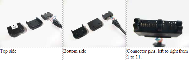
Data cable Wiring
Here is a wiring overview of data cable
- Data to Phone (Rx)
5. Data from Phone (Tx)
9. Test & Flash. NOT CONNECTED!
10. Ground
11. +5v for cable circuit
RS232 Serial Port
RS or Recommended Standard-232 is a standard for computer data communications introduced in 1960. Today, the majority of all personal computers have the capability of utilizing this form of data communications.
Officially, RS-232 is defined as the
“Interface between data terminal equipment and data communications equipment using serial binary data exchange.”
This definition defines data terminal equipment (DTE) as the computer, while data communications equipment (DCE) is the modem. A modem cable has pin-to-pin connections, and is designed to connect a DTE device to a DCE device. It specified signal voltages, signal timing, signal function, a protocol for information exchange, and mechanical connectors.
Standards of RS232:
The RS-232 standard supports two types of connectors,
- The 25 pin DB-25 connector
- The 9 pin DB-9 connector
DB-9 connector:
In our project, DB9 connector standard of RS232 is used.
These diagrams show the male and female pin numbering for DB9 sub-miniature connectors. Generally Pin 1 is marked on the front of the connector right next to the pin. Some manufacturers mark each pin number on the plastic housing at the rear of the connector. The male connector has the sticking out.
Pin Configuration of DB-9 Connector:
| DB-9 Pin | IDC internal pin name* |
Name | Dir | Description |
| 1 | 1 | CD | Carrier Detect | |
| 2 | 3 | RXD | Receive Data | |
| 3 | 5 | TXD | Transmit Data | |
| 4 | 7 | DTR | Data Terminal Ready | |
| 5 | 9 | GND | System Ground | |
| 6 | 2 | DSR | Data Set Ready | |
| 7 | 4 | RTS | Request to Send | |
| 8 | 6 | CTS | Clear to Send | |
| 9 | 8 | RI | Ring Indicator |
Sensors
Temperature Sensor (LM35)
Introduction
The LM35 is an integrated circuit sensor that can be used to measure temperature with an electrical output proportional to the temperature (in oC).
Features of LM35
- Calibrated directly in ° Celsius (Centigrade)
- Linear + 10.0 mV/°C scale factor
- 0.5°C accuracy guarantee able (at +25°C)
- Rated for full −55° to +150°C range
- Suitable for remote applications
- Low cost due to wafer-level trimming
- Operates from 4 to 30 volts
- Less than 60 μA current drain
Low self-heating, 0.08°C in still air - No linearity only ±1⁄4°C typical
- Low impedance output, 0.1for 1 mA load
Advantages
- It measures temperature more accurately than a using a thermistor.
- The sensor circuitry is sealed and not subject to oxidation, etc.
- The LM35 generates a higher output voltage than thermocouples and may not require that the output voltage be amplified.
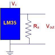
Electrical Connections of LM35
- Here is a commonly used circuit. For connections refer to the picture above.
- In this circuit, parameter values commonly used are:
- i) Vc = 4 to 30v
- ii) 5v or 12 V are typical values used.
iii) Ra = Vc /10-6
Actually, it can range from 80 KW to 600 KW, but most just use 80 KW.
Light Sensor (LDR)
Principle
Light Dependent Resistance [LDR] is a resistance, in which opposing power of current depends on the presence of quantity of light present, i.e. the resistance of LDR increases or decreases, according to quantity of light, which falls on it.
If LDR places in darkness, the resistance of LDR increases and when light falls on it, the resistance of LDR decreases and acts as a conductor. Any LDR in the presence of light and darkness changes its resistance is depends on the different types of LDR.
Advantages
- By using laser, it can be used for security purposes.
- It can be used to stop the wastage of electricity.
- The cost of circuit is low.
- This circuit saves the men’s power.
Light Dependent Resistor Circuits
There are two basic circuits using light dependent resistors.
- The first is activated by darkness.
- The second is activated by light.
The two circuits are very similar and just require an LDR, some standard resistors, a variable resistor (potentiometer), and any small signal transistor.
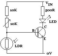
In the above circuit diagram, the LED lights up whenever the LDR is in darkness. The 10K variable resistor is used to fine-tune the level of darkness required before the LED lights up. The 10K standard resistor can be changed as required to achieve the desired effect, although any replacement must be at least 1K to protect the transistor from being damaged by excessive current.
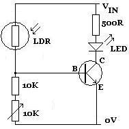
By swapping the LDR over with the 10K and 10K variable resistors (as shown above), the circuit will be activated instead by light. Whenever sufficient light falls on the LDR (manually fine-tuned using the 10K variable resistor),the LED will light up.
The Output Voltage is then passed to 8-bit A/D Converter as the input. The output of the A/D converter is passed to the PC through parallel port. The reading is then evaluated in the software and decision is made based on the maximum and minimum threshold of light intensity, whether to switch on or off lights.
As single A/D Converter is used hence input of this converter must be switched between the two sensing circuits, i.e. Temperature sensing circuit and Light sensing circuit.
IC’s
Microcontroller AT89C51
The AT89C51 provides the following standard features:
- 4K bytes of Flash,
- 128 bytes of RAM,
- 32 I/O lines,
- Two 16-bit timer/counters,
- A five vector two-level interrupt architecture,
- Full duplex serial port,
- On-chip oscillator and clock circuitry
In addition, the AT89C51 is designed with static logic for operation down to zero frequency and supports two software selectable power saving modes. The Idle Mode stops the CPU while allowing the RAM, timer/counters, serial port and interrupt system to continue functioning. The Power-down Mode saves the RAM contents but freezes the oscillator disabling all other chip functions until the next hardware reset.
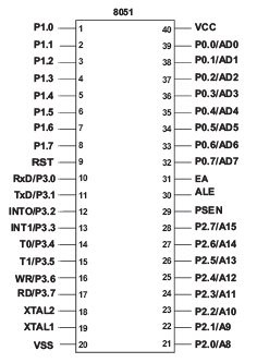
| Pin Number | Description |
| 1 – 8 | P1.0 – P1.7 – Port 1 |
| 9 | RST – Reset |
| 10 – 17 | P3.0 – P3.7 – Port 3 |
| 18 | XTAL2 – Crystal |
| 19 | XTAL1 – Crystal |
| 20 | GND – Ground |
| 21-28 | P2.0 – P2.7 – Port 2 |
| 29 | PSEN – Program Store Enable |
| 30 | ALE – Address Latch Enable |
| 31 | EA – External Access Enable |
| 32-39 | P0.7 – P0.1 – Port 0 |
| 40 | Vcc – Positive Power Supply |
Also read here for complete report
https://eevibes.com/electronics/electronic-circuits/what-are-the-dc-machines/