How to improve the power factor?
How to improve the power factor? This project deals with the power factor improvement and detection as well as deterioration of harmonics by designing an effective harmonic filter for non-linear single phase 220 Volts. Besides the main objectives discussed above it also helps in the protection of electronic devices, gives an idea to implement the theoretical approach on large AC systems such as Grid Stations, High and low level Industries and domestic purposes for energy consumption and efficiency. Hardware consists of power factor improvement by reactive power compensation-Capacitor Banks and Active Harmonic Filter combined or supervised by a PIC Microcontroller for sensing and controlling.
In order to supply electricity effectively to the consumers, the electric power quality plays an important role. Now a day’s power has become an essential and the most valuable resource for the whole earth, the maintenance of power quality has become important, so that the usage of all the appliances and equipment’s could be maintained. Nonlinear loads which are mostly used in industry and also used domestically causes a lot of distortions in current and voltage which causes power losses.
When such distorted voltage and current is applied to equipment it gives poor performance. So during these times when energy demands are increasing every day we cannot afford losses of electricity and also if the quality of power is good the life expectancy and performance of equipment increases drastically.
Factors Affecting Power Quality
The end user decides whether the power quality is good enough or not. If the performance of the equipment is good then the power quality is satisfactory. The power quality would be considered bad if the equipment doesn’t perform well. Given below are the reasons for bad power quality or power quality.
Power frequency disturbances
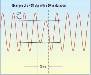
Voltage sags and swells
When the voltage level decreases from its nominal position it causes voltage dip or sag. These voltage sags or dips could last half of a cycle to several seconds. These low voltages are caused from several factors like ups, computers, and flickering, electrical motors.
Induction motors are usually used in industries. These motors when started take a large amount of current which causes decrease in voltage which results in voltage dips or sag. Same thing can be seen in other equipment’s like arc furnaces which take large amount of current initially in order to achieve high temperature. Factors like lightning, birds, contact of trees with power lines and animals to power supply lines causes the utility drops of the voltage.
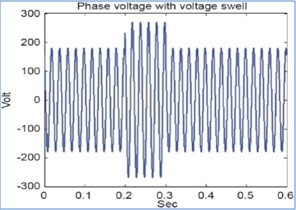
When the loads transfers between sources it causes voltage swells. These can also occur by sudden rejection and application loads. Flickering is a low frequency problem that occurs mainly at low voltage conditions or at starting.
Flickering is caused by low frequencies which can be observed by human eye or low voltages. Mostly the bad performance or malfunction of equipment is caused by voltage sags and swells, which also leads towards loss of efficiency of insulation failures, motors, fluctuation of light illumination, and contractors etc.
If these power frequency disturbances are raised at source level then they not easily cured. But these disturbances can be controlled if they occur internally due to loads. This can be done by separating off end loads from the sensitive loads.
Electrical Transients
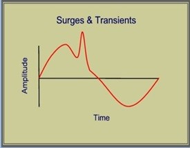
The disturbances which can only last for less than one cycle of AC waveform are called transients. Transients are sub-cycle disturbances. Many factors like limited frequency response or sampling rate make the detection and measurement of transients very difficult.
These transients can also be called as surges, power pulses, spikes, etc. factors like solar flares or atmospheric disturbances causes them to occur. Switching the loads and switching capacitor banks also causes transients.
Transients are kept in mind while designing some of the devices while in most of the cases devices can handle transients which depends on the life expectancy of the equipment’s and severity of transients. These transients can be overcome by using surge protection suppressors, filters and other transient suppressors.
Harmonics
Harmonics in current and voltage is basically the deviation from original sine waves. Harmonic frequencies are integral multiples of fundamental frequency and can be very commonly found in electric power systems like motors, computers and ups etc.
Harmonics can be differentiated on the basis of order into two types. Even types (2, 4, 6, 8, 10) and odd types (3, 5, 7, 9, 11). Odd harmonics are mostly produces in major nonlinear loads. While even harmonics occurs because of the uneven operations of electrical systems e.g. transformer eddy currents etc.
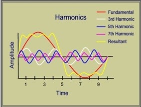
Order of harmonics determine the frequency like 2nd order harmonic has frequency of two times the fundamental frequency. These harmonics are generated by non linear loads like arc furnaces, electric motors, UPS systems etc.
The fundamental waveform is superimposed by odd harmonics, which results in the distorted waveforms. The harmonics produced can seriously effect many electrical systems i.e. overheating of the equipment, interference of communication lines, errors while indicating electrical parameters, probability to produce resonant conditions, etc.
Harmonic analyzer can be used to measure the harmonics and harmonic filters can be used to reduce harmonics. There are two types of harmonic filters which are active and passive filters.
What is the Power Factor?
Power factor is considered as one of the main factors which affect the quality of electrical power. If the power factor is low then it can have severe affects on the electrical equipments, which can result in overheating and in some cases less life of the equipment. It also leads the way to the users being penalized in order to meet electric demands. Power factor can be defined as the ratio of active power to reactive power and determines the amount of electrical power utilization.
Power factor can be explained by an example like if power factor is 0.7, it shows us that that 70 percent of the power is utilized and remaining energy is wasted as losses. Low power factor is due to induction motors, reactive power elements in electrical power system network, etc. So if the power factor is close to 1 then the system will be more efficient.
In order to overcome the low power factor wean se power factor correction devices e.g capacitor banks are main used to overcome power factor problem and other compensation equipments can also be used.
When power factor is improved by capacitor bank it have a strong impact n reducing our energy bills. Here reactive power taken from supply is reduced by capacitors bank which in return offer leading power in nature.
Grounding
The safety of the appliances and their operators depends upon the good power quality. The protection of both system and equipment depends upon grounding. Earth acts as a constant reference potential with one unknown potential which is to be measured.
The equipment’s which are not grounded properly can result in giving shocks to its operators. So grounding is very important as it protects many types of equipment from faults and other un-wanted conditions which occur in electrical power systems.
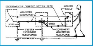
There is a lot of difference between signal reference ground and normal grounding because it doesn’t provide any protection to the systems or the operators. But low impedance path is a necessity so that electronic equipment’s can work properly.
Aims of Project
This prototype is designed for non linear loads like inductors, chokes and motors etc. only domestic loads can be made efficient by using this prototype. In order to obtain better results of harmonics and power factor we implement this prototype on single phase non linear loads. Its purpose is to make energy efficient devices and also to improve the power quality. This design can also be implemented on three phase AC systems which are used on higher levels. During these times of energy crisis world demands more efficient and reservoirs of energy at present and in future. In an underdeveloped country like Pakistan the shortage of energy could lead to poor economy and engineering growths so there is an utmost demand of power engineering solutions like smart and Hybrid grid stations and power improvement techniques.
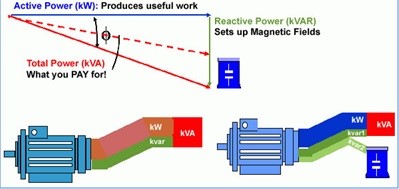
Importance of power factor
Most AC electric machines draw from the supply apparent electricity in phrases of kilovolt amperes (kVA) which is in excess of the beneficial energy, measured in kilowatts (kW), required by using the machine. The ratio of these portions is called the energy thing of the weight, and relies upon the kind of machine in use. Assuming a steady supply voltage, this implies that more modern-day is drawn from the electricity authority than is absolutely required.
Power aspect = (genuine power) / (obvious energy) = kW / kVA
A large proportion of the electrical equipment utilized in enterprise has an inherently low electricity component, because of this that the deliver government must generate a whole lot greater cutting-edge than is theoretically required. This extra modern flows via generators, cables, and transformers inside the identical manner as the useful current. The cause strength necessities are generally more than the resistive loads such as lighting and heating. If steps are not taken to enhance the energy issue of the burden, the entire gadget from the power station to the factory sub-circuit wiring has to be large than important. This results in elevated capital expenditure and better transmission and distribution losses at some point of the entire deliver community.
Tariffs
The bills for electricity are primarily based on various price lists which vary each in structure and fee from place to area. Various status expenses and a connection charge are also made. Generally, the electricity charged for can be primarily based on:
(i) A status price based totally on the overall kilo wattage of the hooked up cars or at the kilo wattage of the most important mounted motor;
(ii) On the quantity of units used;
(iii) a further price for devices while an agreed maximum degree is passed – known as the most call for charge.
The status charge (i) is carried out regardless of the amount of strength consumed or of ways regularly the gadget is used. The rate (ii) is an accumulative charge to take account of the amount of power used in a specific length. Not all gadgets are always charged on the same charge. A meter is provided by the deliver project for this. The maximum demand rate (iii) is a penalty price which is implemented if the amount of energy utilized in a special duration (typically 0.5 hours) exceeds a level which has been formerly agreed between the supplier and consumer. It’s far intended to level out call for by using discouraging users from consuming a large amount of power for just a short time. A separate meter is supplied for this; it measures kVA instead of kW. a few authorities provide reduced tariffs depending upon how and while the energy is used.
Generators
If grid electricity is not available or not suitable in some way, an alternative method of obtaining electricity is to use a generating set. Small sets of a few kVA capacities can be petrol driven, but normally they are diesel-engine driven. The size of the set required depends upon the output required and upon the starting characteristics of the various items of equipment. The supplier of the feed mill machinery can usually advise on the size most suitable for the particular installation.
When the installation consists of a number of small motors, then a set slightly larger than the sum total of the motor kilo wattages is usually adequate, but expressed in kVA based on a power factor normally of 0.8. If however just one of the motors is large in comparison with the total load, a larger generating set is necessary so as to prevent undue voltage dips occurring when that particular motor is started, as such dips will effect equipment already running. For satisfactory operation, the diesel engine will require regular maintenance.
Most people don’t realize that harmonics have been around a long time. Since the first AC generator went online more than 100 years ago, electrical systems have experienced harmonics. The harmonics at that time were minor and had no detrimental effects.
Experimental Work
Project was basically divided into five stages.
- Research
- Planning
- Implementation on Software
- Experimentation on Hardware
- Report Writing
Software or hardware implementation and experimentation encompasses all the processes involved in something operating properly in its environment, including analyzing requirements, installation, configuration, customization, running, testing, systems integrations and making necessary changes.
Experimental work was started on Hardware. Before the Hardware implementation the whole idea was implemented and Designed on a Software (Proteus). Step by step different parts of the hardware were made and checked and then at the end all were combined to make a hardware prototype which reflected our idea.
First of all a basic BLOCK DIAGRAM was made by research. Different Techniques, ideas, calculations and proper guidance of the supervisor led us to finalize the block diagram on early stages. By keeping in mind the basic purpose of the project a block diagram was developed which was further implemented on software. Different blocks were first implemented separately and then at the end a combined software implementation was done. Similar steps were taken for its Hardware implementation.
-
Method and Materials
After developing the block diagram a study was carried out this involved the reading of data sheets of different components which were to be use in the Hardware Prototype. The details of the components used in the Hardware prototype are described as follows:
-
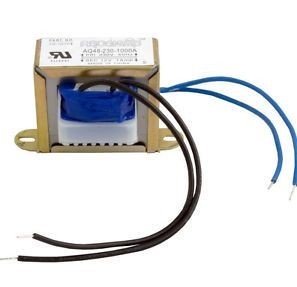
Isolation Transformer
Isolation transformer has a basic function of isolation the electrical system from the Ac power source. This helps in protecting the equipment from electric shocks. Galvanic isolation is provided by isolation transformer which is used in reducing electrical noises. Another use of isolation transformer is that it can provide power transfer between two circuits which are not supposed to be connected. In isolation transformer isolation is present between the secondary and primary wiring and it can bear high voltages.
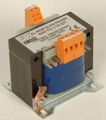
In isolation transformers on AC component is allowed to pass and the entire DC component is blocked. Secondary circuits can be protected if there is 1 to 1 ratio in the transformer.
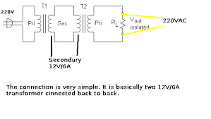
Operation
The designing of isolation transformer is done by keeping in mind the capacitive coupling between primary and secondary windings. Due to the presence of capacitance between the windings it would lead to the coupling of the AC current from primary wiring to the secondary wiring. The coupling of the common mode noise can be reduced if Faraday shield is applied between the two windings.
Current Transformer
Current transformer is basically used to measure current. In CT the alternating current produced in the secondary is proportional to the alternating current produced in the primary winding. Current transformers provides a save environment for the measurement of current using a ammeter by reducing the high voltage alternating current to a very low voltage current. The main functioning principle of the current transformer is same as any other transformer. The only difference is that the CT has only one or very few windings in its primary.
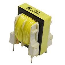
Current transformers are sometimes also called as series transformer because of its arrangement. Main reason of referring CT as current transformer is that it has a few or just one turn in its primary. While the secondary wiring can have a very large number of turns. Usually these secondary windings are rated at 1 or 5 Ampere standards.
What is Potential Transformer?
Potential transformer (PT) which are also known as voltage transformers are used to measure voltages. Unlike current transformers these are connected in parallel. It has a simple functioning of stepping down the high voltage t a very low voltage which in return can be measured by using some specific standards. Unlike CT these transformers have a very large no of coil windings in the primary and small number of turns in the secondary winding.
For full report, click here
power factor improvement project report
Also read here