DC Load Line of Diode: Understanding the Basics
The DC load line is an important concept in electronics that is used to analyze the behavior of electronic components such as diodes. In this article, we will discuss the DC load line of diodes, including the basic concepts, circuit diagrams, and an example.
Basic Concepts of DC Load Line of Diode
A diode is a two-terminal electronic component that allows current to flow in only one direction. It is used in many electronic circuits to rectify AC voltage to DC voltage, voltage regulation, and signal detection. When a diode is forward-biased (positive voltage applied to the anode), it conducts current, and when it is reverse-biased (negative voltage applied to the anode), it does not conduct. The DC load line is a graphical representation of the relationship between the voltage and current in a diode when it is operating under DC conditions. It is a straight line on the voltage-current graph, which shows the diode’s operating point at different voltages and currents.
Circuit Diagram of DC Load Line of Diode
To understand the concept of the DC load line of diodes, let us consider the circuit diagram shown below:
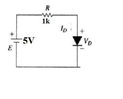
In the circuit diagram, a diode is connected in series with a resistor and a DC voltage source. The resistor R is used to limit the current through the diode, and the voltage source V is used to bias the diode in the forward direction.
Example of DC Load Line of Diode
Let us now consider an example of the DC load line of diodes. Suppose we have a diode with a forward voltage drop of 0.7 V and a maximum current rating of 100 mA. The resistor R is 1 kΩ, and the voltage source V is 5 V.
The first step in analyzing the circuit is to calculate the current through the diode when it is forward-biased. Using Ohm’s law, we can calculate the current as follows:
I = (V – Vf) / R I = (5 – 0.7) / 1k I = 4.3 mA
The second step is to plot the DC load line on the voltage-current graph. The DC load line is a straight line that passes through the point (0, V) and (V/R, 0), where V is the voltage source and R is the resistor value. In this example, the DC load line is shown in red in the graph below:
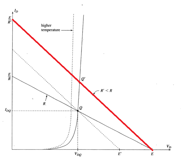
The third step is to find the operating point of the diode on the DC load line. The operating point is the intersection of the DC load line and the diode characteristic curve. The diode characteristic curve is the curve that shows the relationship between the voltage and current of the diode.
In this example, the diode characteristic curve is shown in blue in the graph above. The operating point is found by drawing a line from the origin that intersects the diode characteristic curve. The operating point is the point where this line intersects the DC load line. In this example, the operating point is at approximately (0.7 V, 4.3 mA).
In conclusion, the DC load line of diodes is an essential concept in electronics that is used to analyze the behavior of diodes under DC conditions. It is a graphical representation of the relationship between the voltage and current in a diode.
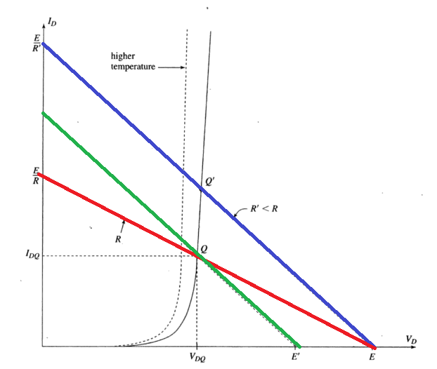
Effect of Temperature on DC Load Line and Q-Point
When the resistance is decreased, while keeping the E constant, the current in the circuit increases as shown with the blue line in the figure. It can be observed that Vd remains as it is (E). Because of this change in temperature, Q-point is also shifted upward represented as Q’. Ir order to bring back the Q-point to its previous value, we will decrease E (as R cant be changed it is of fixed value). We will have to keep the resistance of the circuit fixed now which can be done by keeping the slope of straight line fixed. Then the parallel line drawn in green color shows the same resistance but with decreased value of E. We will keep decreasing the value of E until the actual (previous) Q-point is obtained.
Diode Circuit Example with Time Dependent Voltage Source