How to Design a 4-bit Magnitude Comparator? In this article you will learn about how to design a 4-bit magnitude comparator circuit and how their Boolean function equations are derived. Then I have generalized this concept to n-bit comparator. Also a video lecture is shared at the end for better understanding the idea.
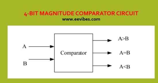
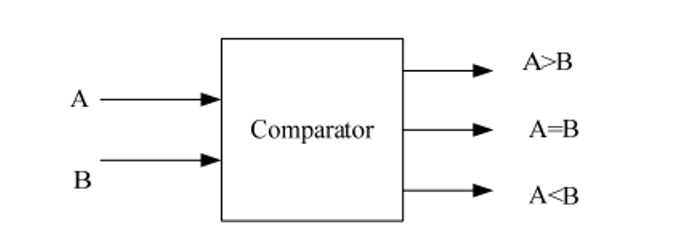
A comparator is a circuit that compares the magnitude of two numbers. The comparison of two numbers is a logical operation that defines whether one number is greater than, less than, or equal to the other number. A magnitude comparator is a combinational circuit that determines the relative magnitudes of given two numbers A and B by comparing them. The result of the comparison is stated by three binary variables that indicate whether these two numbers are:
- A > B
- A = B
- A < B
1 bit Magnitude Comparator
The following table shows how the 1-bit magnitude comparator circuit works. By 1-bit magnitude comparator, we mean that we will be comparing two 1-bit numbers A and B.
| A | B | A>B | A<B | A=B |
| 0 | 0 | 0 | 0 | 1 |
| 0 | 1 | 0 | 1 | 0 |
| 1 | 0 | 1 | 0 | 0 |
| 1 | 0 | 0 | 0 | 1 |
Functions for 1-bit Magnitude Comparator Circuit
A=B=A’B’+AB= A XNOR B
A>B=AB’
A<B=A’B
2-bit Magnitude Comparator Circuit
| A1 | A0 | B1 | B0 | A=B | A>B | A<B |
| 0 | 0 | 0 | 0 | 1 | 0 | 0 |
| 0 | 0 | 0 | 1 | 0 | 0 | 1 |
| 0 | 0 | 1 | 0 | 0 | 0 | 1 |
| 0 | 0 | 1 | 1 | 0 | 0 | 1 |
| 0 | 1 | 0 | 0 | 0 | 1 | 0 |
| 0 | 1 | 0 | 1 | 1 | 0 | 0 |
| 0 | 1 | 1 | 0 | 0 | 0 | 1 |
| 0 | 1 | 1 | 1 | 0 | 0 | 1 |
| 1 | 0 | 0 | 0 | 0 | 1 | 0 |
| 1 | 0 | 0 | 1 | 0 | 1 | 0 |
| 1 | 0 | 1 | 0 | 1 | 0 | 0 |
| 1 | 0 | 1 | 1 | 0 | 0 | 1 |
| 1 | 1 | 0 | 0 | 0 | 1 | 0 |
| 1 | 1 | 0 | 1 | 0 | 1 | 0 |
| 1 | 1 | 1 | 0 | 0 | 1 | 0 |
| 1 | 1 | 1 | 1 | 1 | 0 | 0 |
On the one hand, the circuit for comparing two n -bit numbers have 22n entries in the truth table and becomes too clumsy, even with n = 3. On the other hand, as one may suspect, a comparator circuit holds a certain amount of regularity. Digital functions that possess an inherent well-defined regularity can generally designed by means of an algorithm—a method which specifies a finite set of steps that, if followed, give the result to a problem. We determine this method here by deriving an algorithm for the design of a 4-bit magnitude comparator.
Also see 3-bit magnitude comparator circuit here:
What is the magnitude comparator circuit? Design a 3 bit magnitude comparator circuit
Algorithm of 4-bit comparator:
The algorithm is a direct application of the method a person uses this method to compare the relative magnitudes of two numbers. Now let us consider two numbers, A and B, with four digits each. Then, write the coefficients of the numbers in descending order. It comprises of eight inputs each for two 4- bit numbers to generate three outputs that are less than, equal to and greater than in between two binary numbers.
Inputs of a 4 bit magnitude comparator:
A = A3 A2 A1 A0
B = B3 B2 B1 B0
Each subscripted letter signifies one of the digits in the number. The two numbers are said to be equal if all pairs of significant digits are equal:
A3 = B3, A2 = B2, A1 = B1, and A0 = B0.
Equality of two numbers:
- When the numbers are binary, than the digits are either equal to 1 or 0, and the equality of each pair of bits can be stated logically with an XNOR function as:
XOR-Invert = (AiB’i + A’iBi)’
(A’i + Bi)(Ai + B’i)
A’iAi + A’iB’i AiBi + BiB’i
xi = AiBi + A’iB’I for i = 0,1,2,3
Where xi = 1 only if the pair of bits in position i are same (i.e., if both are 1 or both are 0).
The equality of the two numbers A and B is showed in a combinational circuit by an output binary variable that we term by the symbol (A = B). This binary variable is equal to 1 if the given input numbers, A and B, are same, otherwise is equal to 0. For equality to be present, all xi variables must be equal to 1, a condition that dictates an AND Operation of all variables
(A = B) = x3 x2 x1 x0
The binary variable (A = B) is equal to 1 only if all pairs of significant digits of the given two numbers are same.
Two numbers are greater or less than :
To illustrate whether A is greater than or less than B, we check the relative magnitudes of pairs of significant digits, starting from the most significant digit. If the two digits of a pair are same, we compare the next lower significant pair of digits. The comparison continues till a pair of unequal digits is reached.
- If the corresponding digit of A is equal to 1 and that of B is equal to 0, we conclude that A > B. The sequential comparison can be expressed logically by the Boolean function:
(A > B) = A3 B’3 + x3A2 B’2 + x3x2A1B’1 + x3x2x1A0B’0
- If the corresponding digit of A is equal to 0 and that Of B is equal to 1, we have A < B. The sequential comparison can be expressed logically by the Boolean function:
(A < B) = A’3 B3 + x3A’2 B2 + x3x2A’1B1 + x3x2x1A’0B0
Truth table of 4-bit Comparator:
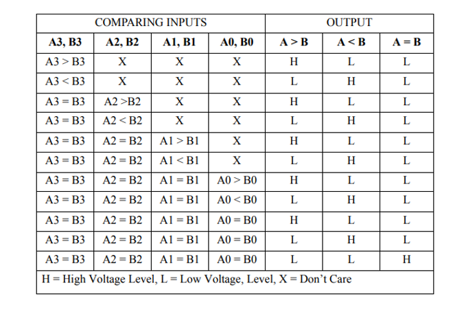
The terms (A > B) and (A < B) are binary output variables and they are equal to 1 when A > B and A < B, respectively.
The gate implementation of the three output variables that is not derived here but it is simpler than it looks because it contains a specific amount of repetition in it. The unequal outputs can also use the same gates that are needed to generate the equal output.
also see
How to determine the overflow of signed and unsigned numbers?
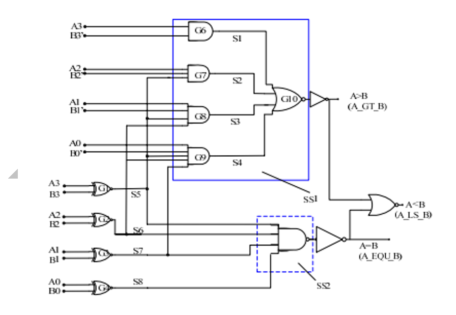
Logic diagram of 4-bit magnitude comparator:
The logic diagram of the 4-bit magnitude comparator is shown in the below diagram. The four x outputs are created with XNOR circuits and are applied to an AND gate to give the output binary variable (A = B) The other two outputs use the x variables to generate the Boolean functions shown previously. This implementation is a multilevel implementation and it has a regular pattern.
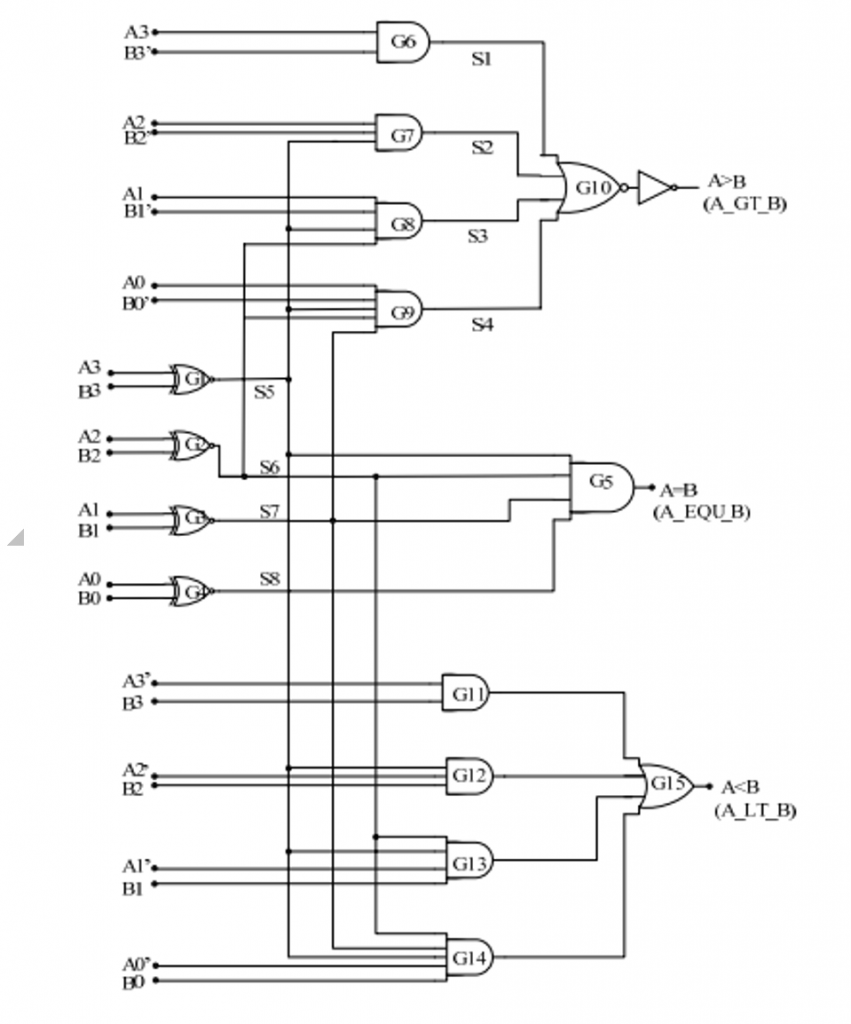
Optimized Logic diagram of 4-bit magnitude comparator:
From this logic diagram we can see that total 11 gates have been used for the implementation of 4-bit comparator beside the inverters. The type of gates includes XOR, AND, NOR. There are 4 XOR gates used with the same inputs. There are 5 gates of AND or NOR used with the different number of inputs but in both of them the principal of layout is same.
Also Check: How to Design Counters Using Sequential Circuits?
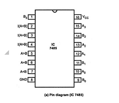
Pin diagram of 4-bit Comparator:
The 4-bit comparator is frequently available in IC form and common type of this IC is 74LS85. This IC can be used to compare two 4-bit binary digits by grounding I (A>B), I (A<B) and I (A=B) connector inputs is given to Vcc terminal. The figure below shows the pin diagram of IC 74LS85 comparator. In addition to the ordinary comparator, this IC is provided with cascading inputs in order to enable the cascading several comparators. We can compare any number of bits by cascading several of these comparator ICs.
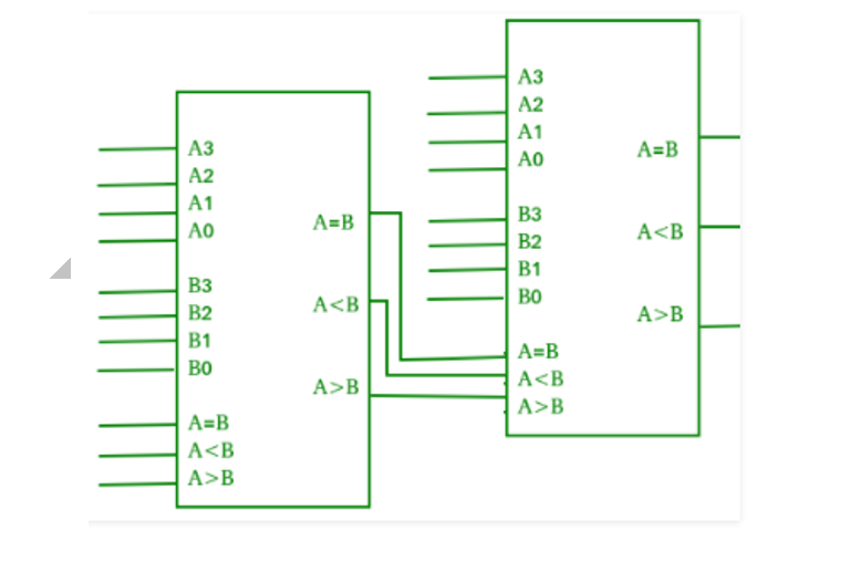
Cascading Comparator:
A comparator executing the comparison operation to more than four bits by cascading. When there are two or more 4-bit comparators they are called cascading comparator. When two comparators are to be cascaded, the outputs of the lower-order comparator are connected with the corresponding given inputs of the higher-order comparator.
For assignments and task, click here
How to perform Packed BCD to ASCII conversion?
Applications of 4-bit Comparator :
- 4-bit comparators are mostly used in electronic devices such as central processing units (CPUs) and microcontrollers (MCUs).
- Comparators are commonly used in control applications in which the physical variables are representing with binary numbers such as temperature and position, etc. and they are compared with some standard value.
- Comparators are widely used as process controllers and for Servo motor control.