Brief Introduction to registers that are used for serial communication in PIC
PIC MICROCONTROLLER :
Registers that are used for serial communication in PIC. PIC is a family of microcontrollers developed by Microchip Technology, available at PIC1650. was first developed by the General Instrument’s Microelectronics Division. The term PIC was originally referred to Peripheral Interface Controller, and is now being expanded as Programmable Intelligent Computer. The first parts of the family were found in 1976; in 2013 the company had shipped more than 12 billion units separately, which are used in various embedded systems.
The first versions of PIC had a read-only memory (ROM) or EPROM programmed in the application field, some with the memory eraser. All current models use flash memory at the end of the program, and newer models allow PIC to reboot. System memory and data memory are separated (see Harvard configuration). Data memory is 8-bit, 16-bit, and, in recent models, 32-bit wide. The program instructions vary by a minimum calculation for the PIC family, and may be 12, 14, 16, or 24 bits long. The tutorial set also varies by model, with very powerful chips that add to the instructions for digital signal processing tasks.
PIC MICROCONTROLLER USED?
PIC microcontrollers (Programmable Interface Controllers), electrical circuits can be programmed to perform a variety of functions. They can be programmed to timely or control the production line and much more.
PIC MICROCONTROLLER REGISTER :
A register is a place within a PIC that has been reading or writing data / program. PIC memory is divided into a series of registers. Each registry has its own address and memory locations. These addresses are usually displayed using hexadecimal numbers.
REGISTER USED FOR SERIAL COMUNICATION :
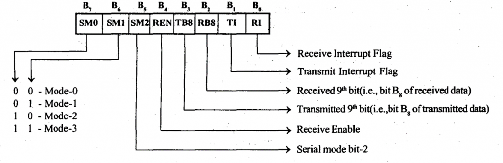
All methods are controlled by SCON, the Serial Control register. SCON bits are defined as SM0, SM1, SM2, REN, TB8, RB8, TI, RI from MSB to LSB. Time estimates are controlled using TMOD, Timer MODe register, and TCON, Timer Control register.
SERIAL PORT CONTROL REGISTER (SCON) OF 8051/8031 MICROCONTROLLER :
- The SCON register type is displayed.
-
Mode 0:
- In this mode the function of port port as port duplex serial port with limited baud rate
- 8- bit serial data is received and transmitted via the RxD pin and the controller releases the TxD pin switch during reception and transfer.
- The baud level is adjusted to 1/12 of the oscillator frequency.
-
Mode 1:
- In this mode the port function as a full duplex serial port with variable baud rate.
- In this mode one data contains 10 pieces, including one start, eight data points and one bit bit. At the time of receipt the stop bit is maintained as RB8 in the SCON register.
- Baud rate in mode 1 depends on the SMOD bit value in the PCON register and the timer1overflow rate. Brief Introduction to registers that are used for serial communication in PIC
-
Mode 2:
- In this mode the serial port function as a full duplex serial port with a baud rate of 1/32 or 1/64 of the oscillator frequency.
- In this mode one data contains 11 pieces including one start, eight data, 9 data set and one bit bit.
- At the time of TB8 transfer the SCON register is entered as 9th data bit and at the time of receipt the 9th data bit is stored as RB8 in the SCON register.
- Baud rate depends on the SMOD bit value in the PCON register.
-
Mode 3:
- Mode 3 is the same as mode 2, except for the baud level.
- In Mode 3, the baud rate varies. The baud rate depends on the SMOD bit value in the PCON register and the 1 time multiplication rate.
- Serial mode bit-2 (SM2) has no effect on mode 0 and if set to mode 0, SM2 should be equal to zero.
- In Mode 1, SM2 is used to check the correct position during reception. In mode 1, if SM2 = 1, then you get the interference (RI) is activated only when the stop bit is detected.
- In Mode 2 and Mode 3 the SM2 bit is used to enable multiple connections.
- For multiprocessor connections a serial port with a number of microcontroller numbers can be connected to a standard serial bus. One controller will act as master and the other control will act as a slave.
- A unique 8-bit address is assigned to each slave and the SM2 bit for all slaves is set to 1.
- If the SM2 bit is a single item, slaves will view the acquired byte as an address and in the case of SM2 bit zero the slaves will view the acquired byte as data.
- Communication with the slave master will first send as a byte of address and then a data byte.
- The master begins to communicate with the slave by sending the slave’s address to the bus. All slaves will receive an address byte. As SM2 = 1 initially for all slaves, the byte received will be considered as an address and the slaves will verify that the received address matches the allotted address. The slave whose assigned address is the same as the address received will slightly erase his SM2. Now the SM2 bit of only one slave will be zero.
- Next the master will send a byte of data which is also received by every slave, but the byte of data is accepted by the slave with SM2 = 0 so the acquisition interruption applies to only one slave with SM2 = 0 of it.
- After reading the information obtained from the SBUF register, the SM2 slave servant must be re-assigned to receive the following information.
- The REN bit of the SCON register can be used to enable or disable serial reception. When REN = 1, serial acceptance is enabled and when REN = 0, serial acceptance is disabled.
- The bits TI and RI of the SCON register transmit the interference flag and receive the interference flag respectively.
- The controller will set the TI bit during data transfer pause in data mode 1 to 3 and during 0-bit data transfer for character 0 mode.
- The controller will set the RI bit during the data acquisition in data mode in mode 1 to 3 and during the receipt of the 8th data character in mode.
Also read here
what is the difference b/w synchronous & asynchronous communication?