What are the external hardware interrupts?
What are the external hardware interrupts? There are two types of external hardware interrupts:
- INTO
- INT1
ACTIVATION OF EXTERNAL INTERRUPTS
The 8051 has 2 external hardware interrupts. Pin (P3.2) and pin thirteen (P3.3) of the 8051, selected as INTO and INT1, area unit used as external hardware interrupts. Upon activation of these pins, the 8051 gets interrupted in irrespective of it’s doing and jumps to the vector table to perform the interrupt function. during this section we’ve an inclination to review these 2 external hardware interrupts of the 8051.
ACTIVATION OF INTO AND INT1
External interrupts INTO and INT1. There unit solely 2 external hardware interrupts within the 8051: INTO and INT1. they’re situated on pins P3.2 and P3.3 of port three, severally. The interrupt vector table locations 0003H and 0013H unit overpassed for INTO and INT1, severally. As mentioned in Section eleven.1, they’re enabled and disabled victimisation registered.
There are two kinds of measurement activation:
-
LEVEL TRIGGERED
-
EDGE TRIGGERED
Let’scheck informed all. First, we’ve bent towork out however the level-triggered interrupt works.
-
LEVEL TRIGGERED
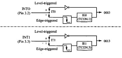
In the level-triggered mode, INTO and INT1 pins unit of measurement ordinarily high (just like all I/O port pins) and if a low-level signal is applied to them, it triggers the interrupt. Then the microcontroller stops regardless of it’s doing and jumps to the interrupt vector table to service that interrupt. this can be often remarked as a level-triggered or level-activated interrupt and is that the default mode upon reset of the 8051.
The low-level signal at the INT pin should be removed before the execution of the last instruction of the interrupt function, RETI; otherwise, another interrupt are visiting be generated. In alternative words, if the low-level interrupt signal isn’t removed before the ISR is finished it’s understood as another interrupt and also the 8051 jumps to the vector table to execute the ISR over again. Check with example:
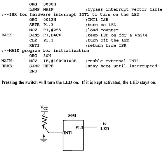
EXAMPLE:
Assume that the INT1 pin is connected to a switch that’s normally high. Whenever it goes low, it should activate an LED. The LED is connected to PI .3 and is often off. When it’s turned thereon should stay for a fraction of a second. As long because the switch is pressed low, the LED should continue.
.In this program, the microcontroller,is looping continuously within the HERE loop. Whenever the turn on INT1 (pin P3.3) is activated, the microcontroller gets out of the loop and jumps to vector location 0013H. The ISR for INT1 activates the LED, keeps it on for a long time, and turns it off before it returns.
If by the time it executes the RETI instruction, the INT1 pin remains low, the microcontroller initiates the interrupt again. Therefore, to finish this problem, the INT1 pin must be brought back to high by the time RETI is executed.
-
EDGE TRIGGERED
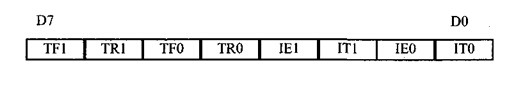
As stated before, upon reset the 8051 makes INTO and INT1 low-level triggered interrupts. to create them edge-triggered interrupts, we must program the bits of the TCON register. The TCON register holds, among other bits, the ITO and IT1 flag bits that determine level- or edge-triggered mode of the hardware interrupts.
ITO and IT1 are bits DO and D2 of the TCON register, respectively. they’re also said as TCON.O and TCON.2 since the TCON register is bit-addressable. Upon reset, TCON.O (ITO) and TCON.2 (III) are both Os, meaning that the external hardware interrupts of INTO and INT1 pins are low-level triggered.
By making the TCON.O and TCON.2 bits high with instructions like “SETB TCON. 0″ and “SETB TCON. 2″, the external hardware interrupts of INTO and INT1 become edge-triggered. for instance, the instruction “SETB CON. 2″ makes INT1 what’s called an edge-triggered interrupt, in which, when a high-to-low signal is applied to pin P3.3, during this case, the controller are interrupted and made to leap to location 0013H within the vector table to service the ISR (assuming that the interrupt bit is enabled within the IE register).
TF1 TCON.7 Timer 1 overflow flag. Set by hardware when timer/counter 1
overflows. Cleared by hardware because the processor vectors to the interrupt routine.
TR1 TCON.6 Timer 1 run control bit. Set/cleared by software to show
timer/counter 1 on/off.
TF0 TCON.5 Timer 0 overflow flag. Set by hardware when timer/counter 0
overflows. Cleared by hardware because the processor vectors to the routine.
TR0 TCON.4 Timer 0 run control bit. Set/cleared by software to show
timer/counter 0 on/off.
IE1 TCON.3 External interrupt 1 edge flag. Set by CPU when the
external interrupt edge (H-to-L transition) is detected. Cleared by CPU when the interrupt is processed. Note: This flag doesn’t latch low-level triggered interrupts.
IT1 TCON.2 Interrupt 1 type control bit. Set/cleared by software to
specify falling edge/low-level triggered external interrupt.
IE0 TCON.1 External interrupt 0 edge flag. Set by CPU when external
interrupt (H-to-L transition) edge is detected. Cleared by CPU when interrupt is processed. Note: This flag doesn’t latch low-level triggered interrupts.
IT0 TCON.0 Interrupt 0 type control bit. Set/cleared by software to specify
falling edge/low-level triggered external interrupt.
HOW TO PROGRAM THEM?
The 8051 has two external hardware interrupts. Piri 12 (P3.2) and pin 13 (P3.3) of the 8051, designated as INTO and INT1, are used as external hardware interrupts. Upon activation of those pins, the 8051 gets interrupted in whatever it’s doing and jumps to the vector table to perform the interrupt subprogram. during this section we study these two external hardware interrupts of the 8051 with some examples.
DIAGRAM:
Also read here
what is the difference b/w synchronous & asynchronous communication?