What are negative edge triggered interrupts? How to sample them?
What are negative edge triggered interrupts? How to sample them? What is INTERRUPT? In pic18 interrupt, whenever any device need service of microcontroller the device notifies microcontroller by sending an interrupt to it. On receiving the signal of service ( which is interrupt) microcontroller stops whatever he is doing and serve to device. It depend on the nature of program which sort of service you need. The program which is associative with interrupt is known as “interrupt service routine” (ISR).
Why we need this?
The advantage of it that microcontroller can serve many devices, each device can get service of microcontroller based on priority assigned. Another reason is that the polling method is not much affective because it waste much of microcontroller time by polling devices.
Example:
If we use BTFSS TMR0IF we need to wait until the timer roll over. But in interrupt method we can go through with other task ,and when the TMR01F flag is raised.
ISR:
If we call an interrupt in over program the ISR (interrupt service routine) tell what to do now and where to go. And there is group of memory location that hold the address of ISR which is called interrupt vector.
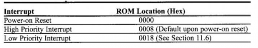
if we set interrupt as high priority it will go towards 0x08 memory location
• If we set it as low it will go to 0x18 memory location.
How an interrupt will work.
We call interrupt within the instruction. Microcontroller will leave it (saved location) and go to the interrupt vector to take address, then it will go to the ISR. After completing the interrupt routine it will go back to the program instruction where he has before.
Negative edge triggered interrupt:
What are negative edge triggered interrupts? How to sample them? There are further two sort of interrupts positive edge triggered and negative edge triggered. To implement these we have some instructions and by little bit changing we use either of it.
For edge triggering interrupt there are three pins that will be use for this purpose
1) INT0
2) INT1
3) INT2
These are on the location of portB0, portB1, portB2 respectively. (for pic18f458/452)
By default these three pins can interrupt as positive edge triggered. But it can be change and convert it into negative edge triggered interrupt by programming in following bit
INTEDGx ( where x can be 0, 1, 2, it depends which pin you will be use. If we use INT0, for programming purposes we take INTEDG0). While INTCON2 register will allow the positive and negative edge triggering. INTCON2 holds INTEDG0, INTEDG1, INTEDG2 at D4, D5 and D6 bits respectively.
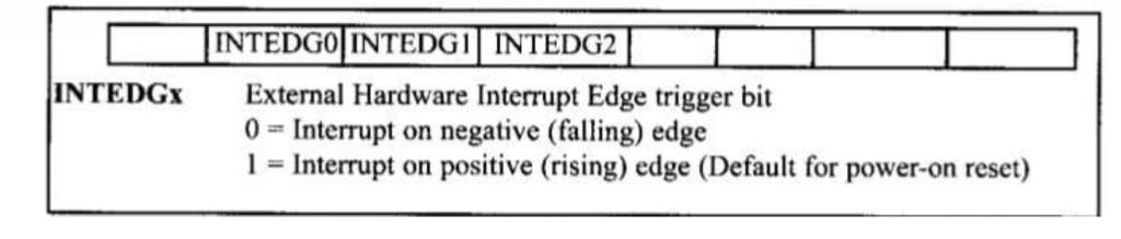
So the status of these three bits INTEDGx can determine whether it will be positive edge trigger or negative edge trigger mode of hardware interrupt.
• If it is one, there is positive edge trigger.
• If the value is zero there is negative edge trigger.
If we reset these, it will make INTEDGx has all 1s and it means external hardware interrupt of INT 0, 1, 2 are positive edge trigger. By making the INTEDGx low ( zero ), it means external hardware interrupts of INT 0,1,2 are negative edge trigger. For making negative; we need to provide the following command.
“BSF INTCON2, INTEDG0”
It makes INTEDG0 a negative edge trigger interrupt in which when a high to low signal is applied to pin portb0 (RB0) the controller will interrupts and force to jump to location of 0x08 in vector table to service the ISR ( but make sure GIE AND INT0IE bits are enable).
For better understanding let take an example. We assume that pin RB1 (INT1) is connected to the pulse generator and RB7 is connected to led. We need to toggle the led on the falling edge of pulse.
ORG 0000H
GOTO MAIN
ORG 0008H
BTFSS INTCON3, INT1IF ; if condition true goto INT1 interrupt
RETFIE ; if not return to main
GOTO INT1 ISR
ORG 00100H
MAIN BCF TRISB, 7 ; PB7 as an output
BSF TRISB, INT1 ; INT1 as input
BSF INTCON3, INT1IEBCF ; enable interrupt
BCF INTCON2, INTEDG1 ; making of negative edge trigger
BSF INTCON, GIE ; enable interrupt globally
OVER BRA OVER
INT1 ISR
ORG 200H
BTG PORTB, 7 ; toggle on RB7
BCF INTCON3, INT1IF ; clear interrupt bit flag
RETFIE
END
Sampling the edge triggered:
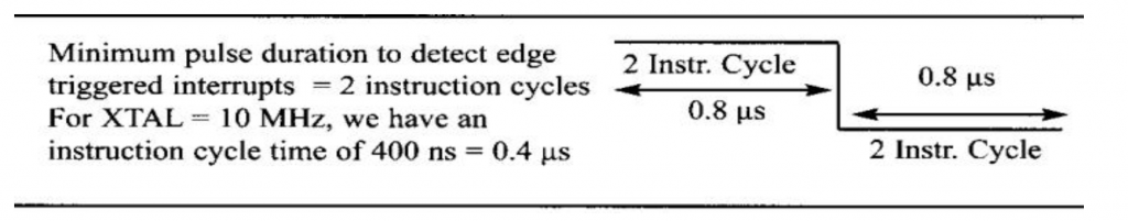
In edge trigger interrupts, the external source must be held high for at least two instruction cycles, and then low for another at least two instruction cycles to insure that the transmission is monitor by controller.
- The rising and falling edge is latch by pic18 and held by INT01F, INT1IF and INT2IF and these bits are hold rising or falling depending on INTEDGx ( from RB0 to RB2 )
- The INTxIF bits function as interrupt in service flags. When interrupt service flag is raised, its means external hardware device is being served on a specific pin INTx and this pin cannot be further use until it complete their task to serve external hardware.
- After completing the interrupts, these INTxIF must be cleared before executing of instruction RETFIE. This indicates that interrupt is finished now and PIC18 microcontroller is ready to respond another interrupt.
- For another interrupt, the pin must be go back to a logic low state and brought back to high to considered a positive triggered interrupt.
Also read here
https://eevibes.com/computing/introduction-to-computing/what-are-the-external-hardware-interrupts/