What are the Rotate Instructions in PIC Microcontroller?
Rotate instructions:
In many applications, there is a need to perform a bitwise rotation of an operand. In the PIC18 there are 4 rotation instructions. They allow a program to rotate a file register to left or right. These rotating instructions have numerous applications. One rotation is simple of the bits of the file register, while the other is a rotation through carry. These instructions are explained below.
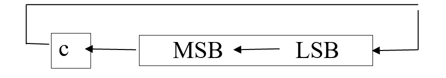
- RRCF (Rotate Right f through Carry Flag)
Syntax: RRCF filereg, d
Operands: 0<= f <= 255
Status affected: C, N ,Z
Explanation: in RRCF, as bits are rotated from left to right, the carry flag enters the MSB and the LSB exits to the carry flag. In other words, in RRCF the C is moved to the MSB, and the LSB is moved to the C. In reality the carry flag acts as if it is part of the register, making it a 9-bit register. .
Encoding:
| 0011 | 00da | ffff | ffff |
Words: 1
Cycles: 1
Example: RRCF REG, 0, 0
Before instruction:
REG = 1110 0110
C = 0
After instruction:
REG = 1110 0110
W = 0111 0011
C = 0
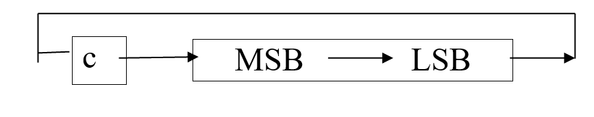
- RLCF (Rotate Left through Carry Flag)
Syntax: RLCF filereg, d
Operands: 0<= f <= 255
Status affected: C,N ,Z
Explanation:
In RLCF, as bits are shifted from right to left, the carry flag enters the LSB and the MSB exists to the carry flag. In other words, an RLCF the C is moved to the LSB, and the MSB is moved to the C.The contents of register F are rotated one bit to the left through the carry flag. If D is 0 the result is placed in W. If D is 1 the result is stored back in register F by default. If a is 0 the Access Bank will be selected, overriding the BSR value. If a = 1, then the bank will be selected as per the BSR value by default.
Encoding:
| 0011 | 01da | ffff | ffff |
Words: 1
Cycles: 1
Example: RlCF REG, 0, 0
Before instruction:
REG = 1110 0110
C = 0
After instruction:
REG = 1110 0110
W = 1100 1100
C = 1
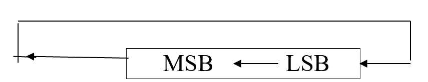
- RRNCF (Rotate Right f no Carry Flag)
Syntax: RRNCF filereg ,d
Operands: 0<= f <= 255
Explanation: in rotate right, the 8 bits of the file register are rotated right one bit, and Beth DO exits from the least significant bit and enters into D7 the most significant bit. After the rotation the result can be in file register or WREG, depending on the d bit. The contents of register F are rotated one bit to the right. If D is 0, the result is placed in W. If D is 1 the result is placed back in register F by default. If a is 0, the excess bank will be selected, overriding the BSR value if a is 1, then the bank will be selected As for BSR value by default.
Encoding:
| 0011 | 00da | ffff | ffff |
Words: 1
Cycles: 1
Example: RRNCF REG, 1, 0
Before instruction:
REG = 1101 0111
After instruction:
REG = 1110 1011
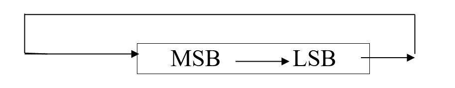
- RLNCF (Rotate Left f no Carry Flag)
Syntax: RLNCF fileReg, d
Operands: 0<= f <= 255
Status affected: N ,Z
Explanation: RLNCF in rotate left, the 8 bits of the file register are rotated left one bit, and bit these seven exits from the MSB which is the most significant bit and enters into DO the least significant bit. After the rotation, the result can be in file register or WRED, depending on the D bit.
MREG EQU 0X20;
MOVLW 0x72; WREG = 0111 0010
MOVWF MYREG;
RLNCF MYREG, F; MYREG = 1110 0100
RLNCF MYREG, F; MYREG = 1100 1001
The contents of register F are rotated one bit to the left through the carry flag. If D is 0 the result is placed in W. If D is 1 the result is stored back in register F by default. If a is 0 the Access Bank will be selected, overriding the BSR value. If a = 1, then the bank will be selected as per the BSR value by default.
Encoding:
| 0100 | 01da | ffff | ffff |
Words: 1
Cycles: 1
Example: RLNCF REG, 0, 0
Before instruction:
REG = 1010 1011
After instruction:
REG = 0101 0111
What are the Rotate Instructions in PIC Microcontroller?
Data serialization:
Serialization data is a method of sending a byte of data one bit at a time via a single microcontroller pin. There are two methods for serially transferring a byte of data:
- Using the serial port The programmer has very little control over the sequence of data transfer when using the serial port.
- The second method used for data serialization is to transfer data one bit at a time while controlling the sequence of data and the spaces between them. Serial versions are becoming popular in many new generations of devices, such as all CDs, ADCs, and EPROMs, because they take up less space on a printed circuit board. Although we can use standards like IC and CAN, not all devices support them. As a result, we must be familiar with data sterilization using the C programming language.
Example:
Write a program to send out the value 83H serially one bit at a time via RC0. The LSB should go out first:
Program:
#include<PIC18F458.h>
#define PC0 PORTCbits.RC0
Void main (void)
{
Unsigned char conbyte = 0x44;
Unsigned char regALSB;
Unsigned char x;
TRISCbits.TRISC0 = 0;
For (x=0; x<8; x++)
{
PC0 = regALSB & 0x01;
regALSB = regALSB >> 1;
}
}
Also read here for more
What is the maximum frequency signal that can be generated in PIC18F4550 microcontroller?