What are synchronous sequential circuits?
What are synchronous sequential circuits? Discuss with examples. A sequential circuit is a logical circuit where the output of depends on the present value of the input as well as the sequence of past inputs and output.
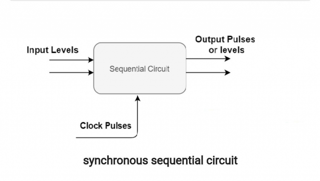
Synchronous Sequential circuits:
The circuit whose behavior can be defined from the knowledge of its signal at discrete instant of time is known as synchronous sequential circuit. Synchronous sequential circuits use level inputs and clock signals as circuit inputs with circuit constraints producing time and beat width to produce performance. A sequential circuit is a logic circuit in which the output depends on the current value of the input and the order of the past inputs and outputs.
Types:
There are two types of synchronous circuit:
- Clocked sequential circuit
- Un-clocked sequential circuit
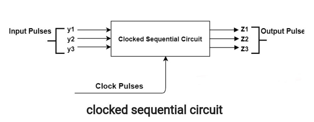
Clocked sequential circuit:
Clocked circuits utilize use flip-flop and gated laches as the memory components. The activity of the circuit is worked by the periodic clock pulse where these are associated with the clock contributions to synchronize every one of the inner changes of the state.
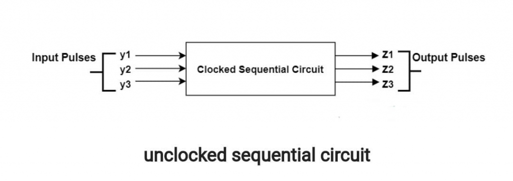
Un-clocked sequential circuit:
This circuit does not require a clock. The internal state change is based on the pulse transition between 0 pulse or 1 pulse. It is designed to act in response to a specific time impulse; periodic signal between the zero signal and the spacer.
Properties of synchronous circuit:
- These circuit are easy to design as compared to other types of sequential circuit,
- A clocked flip flop acts as a memory elements.
- They are slower.
- The status of memory elements is affected only at the active edge of clock, if input is changed.
- They use clock signal.
Application:
Synchronous sequential circuits are applicable in these:
- Counter
- Shift registers
- Storage units
Examples:
Flip flop:
This is an example of a sequential circuit that generates an output from Inputs and Outputs at different time intervals, but not periodically. A flip-flop is an edge-sensitive device.
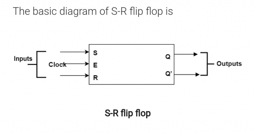
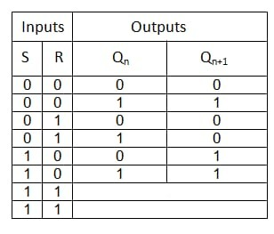
SR flip-flop is formed from the combination of NAND gates and the enable input. The output occurs when the input is active.
Block diagram:
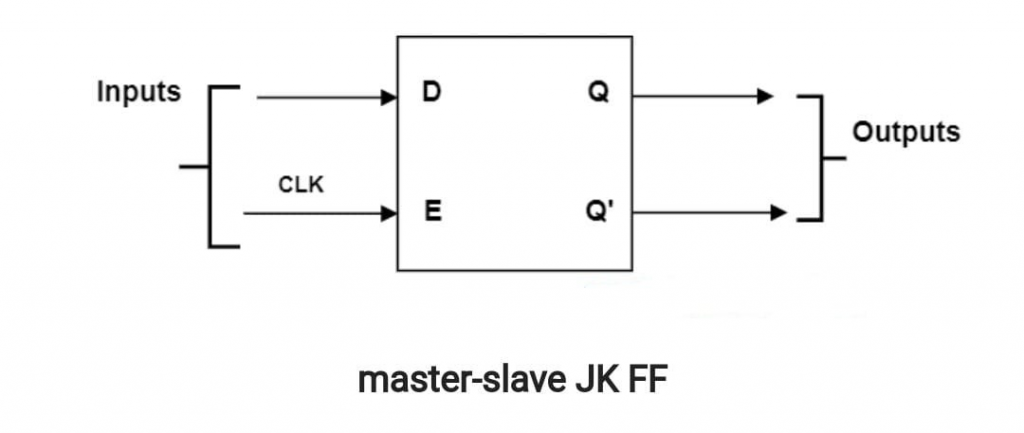
Master- slave: JK flip flop:
This is the combination of two SR flip-flops that connect the received output of the second FF to the first FF. Master is considered the positively activated level. However, if there is a clock line inverter, the slave will only respond at the negative level. If the clock is in state ‘1’, the master is on and the slave is in sleep mode. And when the clock is in state ‘0’, the master becomes inactive and the slave is in active mode.
Diagram:
Its function is correct if its connection is identical to that shown in the following diagram:
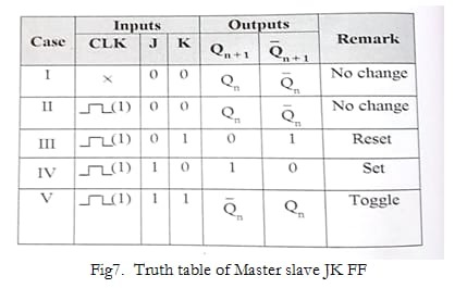
Truth table:
The output is clearly described in the following truth table:
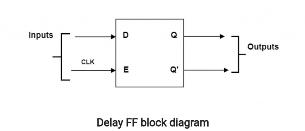
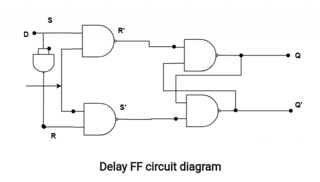
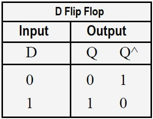
Delay (D)flip flop :
Flip -delay flop is the combination of a simple SR flip-flop with a NAND inverter, which is connected between the S and R inputs. The delay flip-flop has an input and the input information appears at the output after a certain delay. This delay is what this flip-flop calls a delay flip-flop. The input condition will not appear here under the conditions S = R = 0 or S = R = 1
Block diagram:
This is the actual diagram of the delay flip flop:
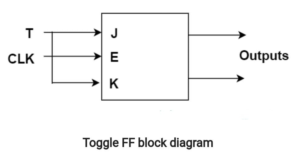
Toggle flip flop:
The Toggle Flip Flop is generally a JK FF with inputs J and K connected. There is only one input here and this flip flop is triggered with positive edges.
Diagram:
This the actual diagram of this:
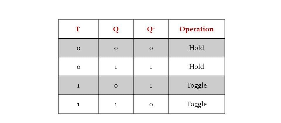
Truth table:
This is truth table of toggle flip flop:
How to Design a sequential Circuit that Detects Three or More Consecutive 1’s in the Input String?
Related topics: