Table of Contents
Discuss the characteristics of ADC in detail
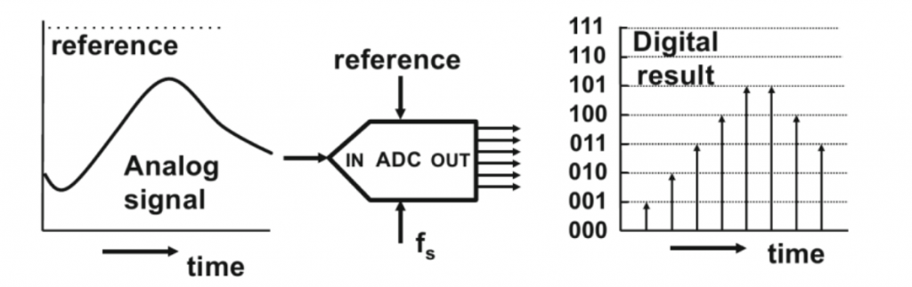
Discuss the characteristics of ADC in detail. ADC stands for analog to digital converter. It is a widely used electrical component. It converts an analog signal into its digital representation. The main component of any digital circuit that needs to process an analog signal is an ADC. The devices which use an ADC to convert analog signals into digital numbers are known as ADC devices. A microcontroller can understand and process only digital numbers. It cannot process analog signals. Transducer is a very widely used example of ADC devices. Transducers are also known as sensors. They convert a physical quantity into electrical signals.
Characteristics of an ADC
Following are the characteristics of an ADC.
1. Resolution
2. Conversion time
3. Vref
4. Digital data output
5. Parallel versus serial ADC
6. Analog input channels
7. Start-conversion and end-of-conversion signals
Now lets briefly discuss these characteristics one by one below.
1. Resolution:
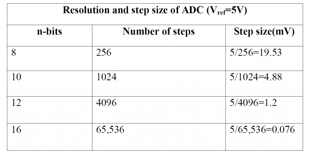
The resolution of a converter represents the number of different values it can produce over the large amount of analog inputs. The maximum ratio of analog to digital conversion without using oversampling is determined by resolution. The input samples are stored in binary form inside the ADC. The resolution of an ADC depends upon the step size. Step size is the smallest change that is done by an ADC. A high resolution ADC has a smaller step size. An ADC has n-bits resolution. ‘n’ can be 8,10,12,16 or even 24-bits. Some widely used resolutions for ADCs are shown in the table below. Although the resolution of an ADC is set at the time of design and it cannot be changed later, we can control step size with the help of Vref.
Conversion time:
Conversion time is another major characteristic of ADC after resolution. It is defined as the time taken by an ADC to convert an analog signal into a digital binary signal. It depends upon the technology used in the ADC. Material of the chip of ADC also effects the conversion time. Method used in data conversion also effects conversion time. Conversion time is measured by a clock attached with ADC. An ADC device has a conversion time of 40μs.
3. Vref:
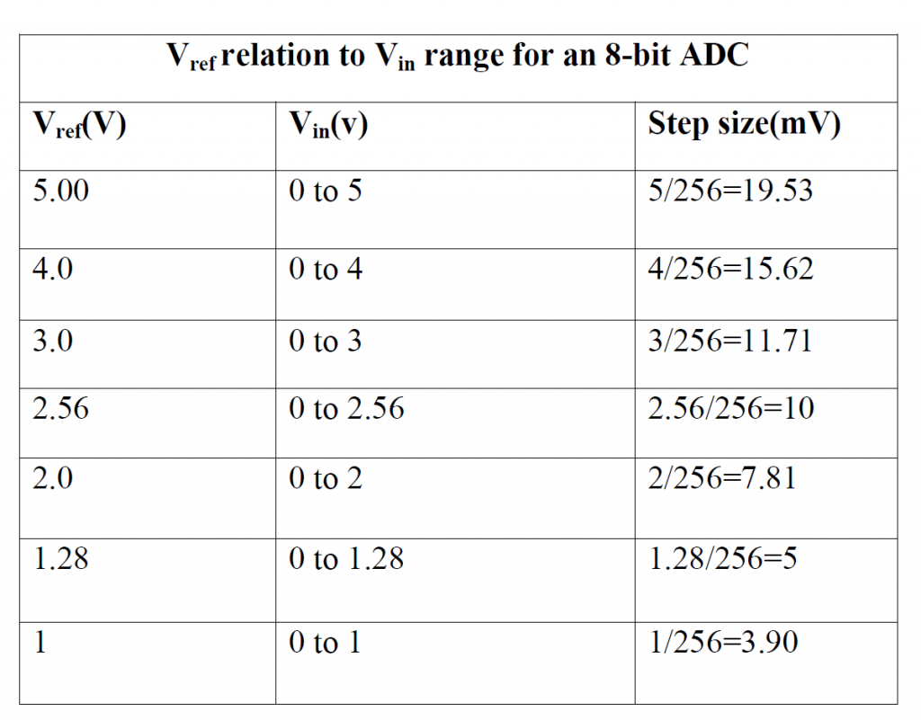
Vref stands for reference voltage. It is one of the input voltages. Step size is determined by reference voltage and resolution. In an 8-bit ADC, step size is Vref/256 because 2 to the power of 8 give us 256 steps. The larger reference voltage we give as input, we get larger value of step size. Their relation is shown in the table below. In some cases, we use differential reference voltage. In this scenario, the overall reference voltage will be the difference of +ve Vref and –ve Vref. usually +ve Vref pin is used as Vref and –ve Vref pin is used as ground.
Digital data output:
Output of an ADC depends on the bits. In 8-bit ADC, we get an output from D0 to D7. In 10-bits ADC, we get an output from D0-D9. Output data depends on the ADC ship. It can come in one bit at a time (serially) or in a chunk when using a parallel line of output. We can calculate data output voltage using the formula given below.
Dout=Vin/step size
Parallel versus serial ADC:
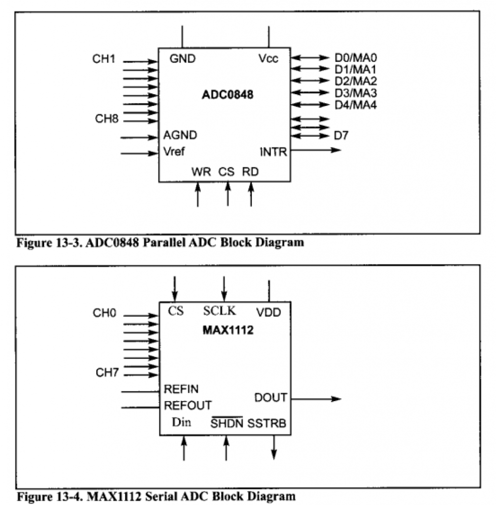
There are two types of ADC i.e. parallel and serial ADC. Parallel ADC gives output in chunks. They have 8 pins for output. D0-D7 gives output between ADC and the CPU in an 8 bit ADC. It is a faster way of getting digital values from analog signal. But it takes too much place on a circuit board. Furthermore, In 16 bit and 24 bit ADCs, we use D0-D7 as output of upper level and lower level values. So it takes too much space. Circuit in which space is an issue, we use serial ADC. Serial ADC is a bit slower in giving output than parallel ADC because it gives one bit at a time as output and we have only one pin for output. Due to this, serial ADCs are widely used in circuits. More CPU time is required in serial ACD than parallel ACD. Diagram of both serial and parallel ACD is as follows.
Analog input channels:
There are certain cases in which more than one ADCs are required. Due to this, ADC chips with 2, 4, 8, or even 16 channels are developed on a single chip. We have 8 channels for analog inputs in these chips. This allows us to monitor different quantities at the same time. Multiplexing of analog inputs is widely used in ADC848. PIC 18 microcontroller chips come with 5-15 ADC channels.
Start conversion and end of conversion signals:
As we have multiple analog inputs and only one digital output register, to function properly we use a sequence of start conversion and end of conversion signals. When start-conversion signals are on, ADC starts converting the analog inputs (Vin) into n digital number. Time of conversion always depends on the method of conversion used. When data is converted, the end of conversion signals tells the CPU that digital output is ready to be delivered.
Related Topics
- What are the conditional and unconditional branches in PIC microcontroller ?
- How to create a first project in PIC microcontroller using assembly language
- How many types of PIC microcontroller are available in market?
- what are the practical applications of embedded systems?
- How to import hex file into PIC microcontroller using PROTEUS
- PIC microcontroller timers programming
- Interfacing of seven segment display with pic16F877A microcontroller
- How to interface LCD with PIC18f4550 microcontroller?
- How to perform serial communication on PIC microcontroller?
- What is the minimum frequency signal that can be generated in PIC18F4550 microcontroller?
- What is the maximum frequency signal that can be generated in PIC18F4550 microcontroller?
- 16 bit timer programming of PIC18 microcontroller
- What is the CCP module of PIC microcontroller?
- What are the timer interrupts of PIC microcontroller?
- How to interface DC motor with PIC microcontroller?
- Briefly write about all pins of LCD for co
- nnecting with the PIC microcontroller
- Interrupt priority of PIC18 microcontroller
- What are the rotate instructions in PIC microcontroller?
- Application of DIV instruction in PIC microcontroller
- How to perform subtraction of unsigned numbers in PIC microcontroller?
- What are the factors that Influence the selection of Embedded Microcontrollers?
- How to program counters in microcontroller?
- How to calculate the time delays in PIC Programming?
- How to differentiate between different types of microcontrollers?
- What is the criteria for choosing a microcontroller?
- How to create a square wave program in PIC using assembly language
- How to interface Stepper Motor with PIC ?
- How to control the direction of DC motor with PIC ?
- what are the assembler directives in PIC?
- How temperature sensor is interfaced with PIC micro controller?
- How keypad is interfaced with PIC Controller?
- Registers that are used for serial communication in PIC
- Embedded Systems Future: Design of optimized Energy Metering Devices