Counter Programming
How to program counters in microcontroller? In this article you will learn about counter programming of PIC microcontroller. Throughout the discussion, we will consider PIC18F4550 microcontroller. There are basically 5 timers available in PIC18 and they can be programmed either as counters or timers. It all depends on their triggering source. If PIC18’s crystal is used as the source of frequency then it will act as a timer. If some external pulse causes an increment in the values of TH/TL then it acts as a counter.
For configuration, TCON ann TMR registers are used.
What is the T0CON register?

This is an 8 bit register and it is used for configurating the timers of PIC. Each bit has its specific role assigned to it.
The first three bits are used for setting the values of prescaler. Timers can be programmed in either 16 bits mode or 8 bits mode. So the maximum attainable value is 256 or 65535. But it we want to introduce more larger delays then we can do this using prescaler idea. In such cases, the OSC frequency is further divided by the prescaler value.
| 0 | 0 | 0 | 1:2 | FOSC/4/2 |
| 0 | 0 | 1 | 1:4 | FOSC/4/4 |
| 0 | 1 | 0 | 1:8 | FOSC/4/8 |
| 0 | 1 | 1 | 1:16 | FOSC/4/16 |
| 1 | 0 | 0 | 1:32 | FOSC/4/32 |
| 1 | 0 | 1 | 1:64 | FOSC/4/64 |
| 1 | 1 | 0 | 1:128 | FOSC/4/128 |
| 1 | 1 | 1 | 1:256 | FOSC/4/256 |
The next bit is PSA: Prescaler Assignment bit. This bit decides either to bypass the prescaler or use it for calculating the delays. If it is equal to 1, then timer0 clock input bypasses the prescaler.
T0CS: timer 0 clock source select bit.
1=External clock will increment the timers registers value (RA4 pin/T0CK input pin)
0=Internal clock source will be used (FOSC/4).
So 4th pin of PORTA is used as a triggering and counting source for timer 0 and similarly for timer1 0 pin of PORTC (RC0) is used. The clock pulses are fed through these pins foe incrementing the count.
Counter Programming Example
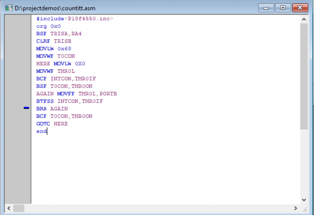
Assume that the clock pulses are fed into the Pin T0CK1, write a program for counter 0 in 8 bit mode to count the pulses and display the state of TMR0L count on PORTB.
BSF TRISA,RA4
CLRF TRISB
MOVLW 0x68
MOVWF T0CON
HERE MOVLW 0X0
MOVWF TMR0L
BCF INTCON,TMR0IF
BSF T0CON,TMR0ON
AGAIN MOVFF TMR0L,PORTB
BTFSS INTCON,TMR0IF
BRA AGAIN
BCF T0CON,TMR0ON
GOTO HERE
MPLAB code for counter programming
Simulations of Counter On Proteus
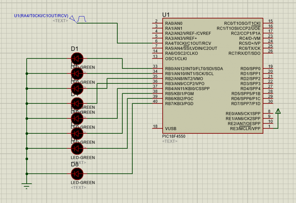
Proteus Simulation of counter Programming of PIC18f4550 Microcontroller
Here is the demonstration of 8 bit counter programming on PROTEUS
Using External clock for TIMER1
Timer1 has two options for its clock source: the first one is the clock fed into T1CK1 pin and the second one is through the crystal connected at the pin T1OS1 and TIOSO pins. This is usually used in SLEEP mode. Becasue the SLEEP mode does not disable the TMR1. Now it should be noted that there are two clock sources available. First clock source is the systems main frequency that is used by the CPU for executing normal instructions and the 32KHz frequency signal when the system is in sleep mode. At that time the system clock is disabled.
This is used for power saving purposes. This allows to implement on chip RTC (Real Time Clock).
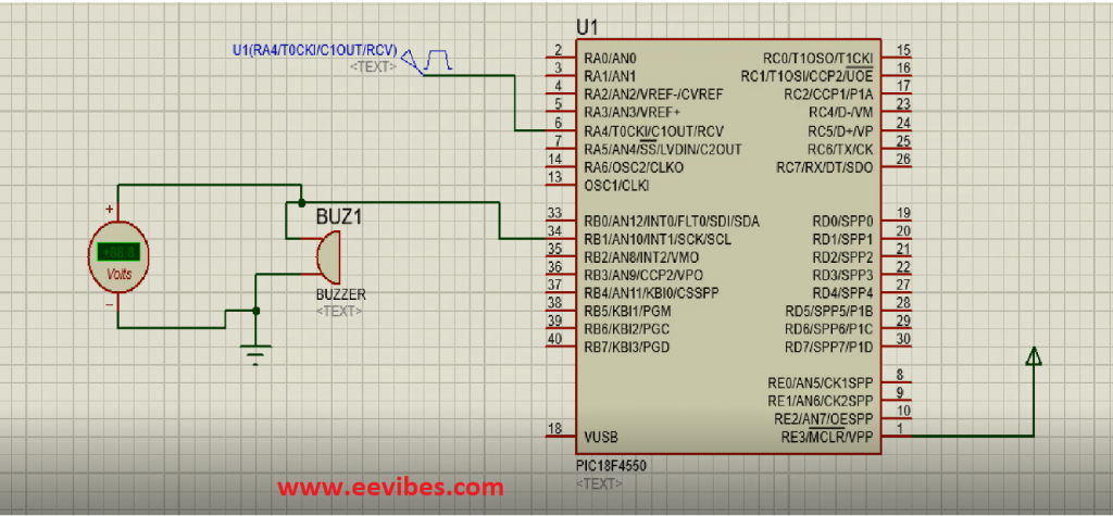
Assume that clock pulses are fed into pin RA4 and a buzzer is connected to pin 1 of PORTB. Write a program for counter 0 in 8-bit mode to sound the buzzer every 100 pulses.
Solution :
#INCLUDE<P18F4550.INC>
ORG 0
BCF TRISB,1
BSF TRISA,4
MOVLW 0X68
MOVWF T0CON
MOVLW -D’100′
MOVWF TMR0L
BCF INTCON,TMR0IF
BSF T0CON,TMR0ON
AGAIN BTFSS INTCON,TMR0IF
BRA AGAIN
BCF T0CON,TMR0ON
OVER BTG PORTB,1
CALL DELAY
GOTO OVER
ORG 0X50
DELAY
R1 EQU 0X10
COUNT EQU D’100′
MOVLW COUNT
MOVWF R1
LABEL DECF R1,F
BNZ LABEL
END
Software simulations for buzzer program
counter programming on PIC Microcontroller
Also read here