What are the Analog Meters?
What are the Analog Meters and their classification? Broadly speaking, analog instruments can be classified in two ways:
- Absolute instruments.
- Secondary instruments
The absolute instruments give the value of the electrical quantity to be measured in terms of instrument constants and their deviation, no comparison with another instrument is required. For example, the tangent galvanometer provides the value of the current that will be measured as a function of the tangent of the deviation angle produced by the current, the radius and the number of revolutions of the galvanometer coil and the horizontal component of the earth’s magnetic field. . . Therefore, it is not necessary to calibrate the instrument.
The secondary instruments are constructed in such a way that the value of the current, voltage or other quantity to be measured can be determined from the deviation of the instruments, only if the latter has been calibrated in comparison with an absolute instrument or is already calibrated . The deviation obtained does not make sense until this calibration has been carried out.
This class of instruments is the most commonly used, and the absolute instrument is rarely used, except in standard laboratories and similar institutions.
Secondary instruments can be classified as
- Indicating instruments
- Recording instruments.
- Instruments of integration.
Indicator instruments are instruments that indicate the magnitude of a measured quantity. They usually use a dial and a pointer for this purpose.
The recording instruments continuously record the quantity measured during a given period. The variations in the measured quantity are recorded by a ballpoint pen (attached to the movement system of the instrument, the displacement system is controlled by the measured amount) on a sheet of paper that moves perpendicular to the movement of the pen.
Integration instruments record aggregate events over a period of time. The sum they give is the product of time and an electric quantity. Ammeters and energy (energy) meters are examples of this category.
Principle of Operation of Analogue Meter
Analog instruments can be classified according to the operating principle they use. The effects they use are
- magnetic effect
- heating effect
- electrostatic effect
- Electromagnetic effect.
- Hall effect
Most analog instruments, including voice coil, moving iron and electrodynamics, use the magnetic effect. The effect of heat generated by a current in a conductor is used in thermocouples and hot wire instruments. The electrostatic effect is used in electrostatic voltmeters. The effect of electromagnetic induction is used in wattmeters and induction energy meters.
Operating Torques
Three types of pairs are required for the correct functioning of any indicator instrument. These are
- return torque
- Torque control
- damping torque
Deflecting Torque/Force
The deviation of an instrument is determined by the total effect of the torque / deflection force, torque / control force and torque / damping force. The value of the deviation torque depends on the electrical signal to be measured; This torque / force helps to rotate the movement of the instrument from its zero position. The system that produces the return pair is called the return system.
Controlling Torque/Force
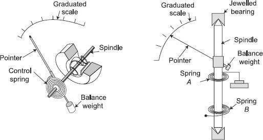
The action of this torque / force opposes the torque / deflection force. When the deviation and control pairs are equal, the movement will be in a defined position or in equilibrium. Spiral springs or gravity are usually given to produce the control torque. The system that produces the control pair is called the control system. The functions of the control system are:
- Produces an equal and opposite torque to the deviation torque in the final fixed position of the needle to define the deviation of the needle for a particular current intensity.
- Return the mobile system to its zero position when the force that causes the deviation of the mobile system of the instrument is eliminated.
The control torque in the indicators is almost always obtained by means of a spring, and much less frequently, by gravity.
Damping Torque/Force
A damping force generally works in a direction opposite to the movement of the moving system. This opposite movement of the damping force, without any oscillation or small oscillation, causes the moving system to rest quickly in the deflected end position. Air friction, fluid friction and eddy currents provide the torsion / damping force to act. It should also be taken into account that the entire damping force does not affect the steady state deflection caused by a given deflection force or torque. With the angular velocity of the system in motion, the intensity of the damping force increases; therefore, its effect is greater when it rotates rapidly and at zero when the rotation of the system is zero. In the description of various types of instruments, the detailed mathematical expressions for the damping pairs are taken into account.
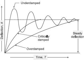
When the deviation torque is much greater than the control torque, the system is called insufficient attenuation. If the deviation torque is equal to the control torque, then it is called critical damping. When the deviation torque is much smaller than the control torque, the system is too damped. The figure shows the variation of the arrow (d) over time for poorly damped, heavily damped and over amortized systems.
Constructional Details
Moving System
The moving system must have the following properties:
- Moving parts must be lightweight.
- The friction force must be minimal.
These requirements must be fulfilled so that the instrument required for its operation consumes little energy. The power is proportional to the weight of the moving parts and the friction forces the opposite movement. The movement system can be made lighter using as much aluminum as possible. Friction forces are reduced by the use of ball bearings mounted on the spindle and the balance of the system.
The force or torque developed by the moving element of an electric instrument is necessarily small to maintain the weak energy consumption of the instrument, so that the introduction of the instrument in a circuit can cause a modification. Minimum of the conditions of the existing circuit. Due to the low power levels, the consideration of different methods to support mobile elements becomes of vital importance. Because the operating force is small, the friction force must be kept to a minimum so that the instrument can read correctly, have an erratic action and be reliable. The supports can be of the following types:
- Suspension
- Tense suspension
- Pivot and jewel bearings.
Suspension
It consists of a thin metal filament in the form of a ribbon for the upper suspension and a coil of thin wire for the lower part. The ribbon is made of a spring material such as beryllium copper or phosphor bronze. This winding of the lower part of the suspension is done so as not to force the system in motion. The type of suspension requires careful leveling of the instrument, so that the moving system is locked in a correct vertical position. Therefore, this construction is not suitable for use in the field and is only used in laboratory applications where a very high sensitivity is required. To avoid shock on the suspension during transport, etc., a clamping device is used to support the system in motion.
Taut Suspension
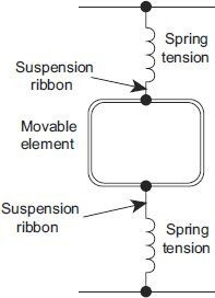
A type of suspension instrument can only be used in a vertical position. The tensioned suspension comprises a flat belt suspension above and below the movable member, the suspension of which is held under tension by a spring arrangement (Figure 2.2). The advantage of this type of suspension is that exact leveling is not necessary if the moving system is correctly balanced.
The suspension of traction and the suspension are used generally in instruments of the class of galvanometer that require a mechanism of low friction and high sensitivity. But in reality, there is no strict dividing line between a galvanometer and other indicator instruments. Some sensitive electrostatic voltmeters and wattmeters use a flexible suspension.
The suspension of the belt, in addition to supporting the mobile member, exerts a control torque during the turn. Therefore, the use of the suspension causes the elimination of pivots, jewels, control springs and, therefore, the instruments without pivot are free of many defects.
Pivot and Jewel Bearings
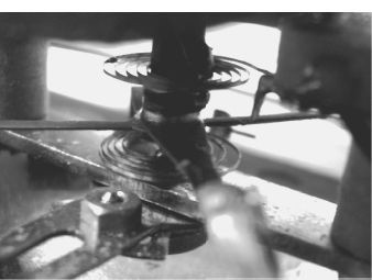
The moving system is mounted on a hardened steel pin. Both ends of the spindle are sharpened and polished to form pivots. These ends adapt to the conical holes of the jewels located in the fixed part of the instruments. These jewels, which are preferably sapphire, form bearings
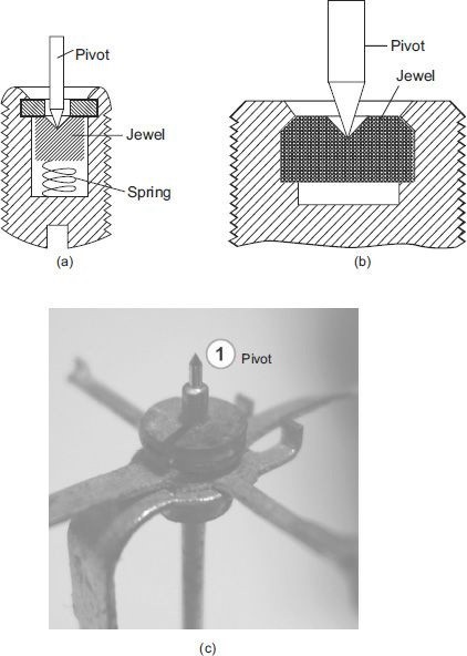
It has been found that the friction torque for the ball bearings is proportional to the contact area between the pivot and the stone. Therefore, the contact area between a pivot and a jewel should be small. The pivot is rectified in a cone and its end is rounded to a small hemispherical surface. The jewel is milled to a slightly larger corner cone.
Torque/Weight Ratio
The friction torque in an instrument depends on the weight of the moving parts. If the weight of the moving parts is important, the friction torque will be important. The friction torque has a considerable influence on the performance of an indicator instrument. If the friction torque is large and comparable to a considerable fraction of the deflection torque, the deflection of the moving system will depend on the friction torque to an appreciable degree. In addition, the deviation will depend on the direction from which the equilibrium position approaches and will be uncertain. On the other hand, if the friction torque is very small compared to the deviation torque, its effect on the deviation is negligible. Therefore, the relationship between the torque of deviation and the friction torque is a measure of the reliability of the indications of the instrument and constitutes the inherent quality of the design. The torque / weight (deviated) ratio of an instrument is an index of its performance. The higher the ratio, the better your performance will be.
Permanent Magnet Moving Coil Instrument
Principle of Operation
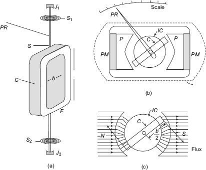
The operating principle of a permanent magnet mobile coil (PMMC) instrument is that a torque is exerted on a conductive coil placed in the field of a permanent magnet. A PMMC instrument is shown in Figure 2.11. The coil C comprises several turns of thin insulated wires wound in a rectangular form of aluminum F. The frame is carried on a pin S mounted on the ball bearings J1, J2. A PR pointer is attached to the axis so that it moves on a calibrated scale. The entire displacement system is as light as possible to minimize friction in the bearing.
The coil can rotate freely in the interstices formed between the soft iron pole piece (PP) of a permanent magnet PM and a cylindrical IC of soft iron [Figure (b)]. The core serves two purposes; (a) intensifies the magnetic field by reducing the length of the space, and (b) makes the field radial and uniform in space.
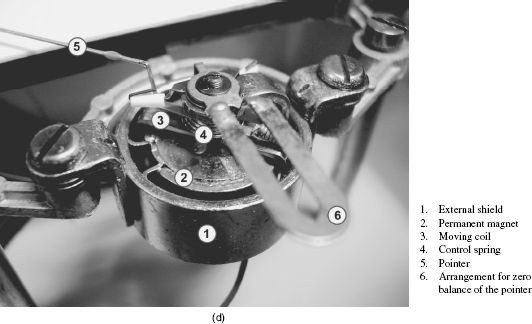
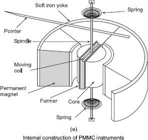
Therefore, the coil always moves perpendicular to the magnetic field [Figure (c)]. Modern permanent magnets are made of difficult-to-machine steel alloys. The polar pieces of soft iron (PP) are attached to the permanent magnet PM to facilitate machining and adjust the length of the air space. Figure (d) shows the internal parts and Figure (e) shows the diagram of the internal parts of a voice coil instrument.
A soft iron yoke (Y) completes the flow path and provides protection against strange external fields.
Advantages & Disadvantages of PMMC Instruments
Advantages of PMMC Instruments
- Sensitive to little present
- Very precise and dependable
- Uniform scale up to 270° or more
- Very viable inherent damping
- Low control utilization, changes from 25 µW to 200 µW
- Free from hysteresis and not affected by outside fields since its lasting magnet shields the loop from outer attractive fields
- Easily embraced as a multi-run instrument
Disadvantages of PMMC Instruments
- This kind of instrument can be worked in direct current as it were. In exchanging current, the instrument does not work in light of the fact that in the positive a large portion of, the pointer encounters a power one way and in the negative a large portion of the pointer encounters the power the other way. Because of the inactivity of the pointer, it holds its zero position.
- The moving framework is sensitive and can without much of a stretch be harmed by harsh taking care of.
- The curl being exceptionally fine, can’t withstand delayed over-burdening.
- It is costlier.
- The maturing of the instrument (lasting magnet and control spring) may present a few blunders
Moving-Iron Instruments
Iron instruments in motion or MI can be classified as
- Wrought iron attraction instruments.
- Iron instruments of the movement type.
In general, the current to be measured passes through a coil of wire in moving iron instruments. In the case of voltage measurement, the current proportional to the voltage is measured. The number of turns of the coil depends on the current to be crossed. For the operation of the instrument, several amplifiers are required. These amplifier turns can be produced by the product of a few twists and strong currents or inverters.
Attraction-type Moving-Iron Instruments
The type of attraction of the MI instrument depends on the attraction of an iron blade in a coil carrying the current to be measured. Figure 2.14 shows an instrument of type MI attraction. An IV soft iron platform is attached to the movement system. When the current to be measured passes through coil C, a magnetic field is generated. This field attracts the eccentric vane mounted on the shaft towards it. The shaft is supported on both ends by a pair of ball bearings. Therefore, the pointer PR, which is attached to the axis S of the moving system, deviates. The pointer moves on a calibrated scale.
The control torque is provided by two springs S1 and S2 in the same way as for a PMMC instrument; but in such instruments, the springs are not used to carry any current. Gravity control can also be used for vertically mounted panel-type MI meters. The damping torque is provided by the movement of a thin V-shaped fin in a box B in the form of a closed sector, or simply by a fin attached to the moving system. The damping of the Foucault current can not be used in MI instruments, since any permanent magnet needed to produce the damping of the eddy current can distort the magnetic field that would otherwise be produced by the coil.
If the current in the fixed coil is reversed, the field generated by it also reverses. Thus, the polarity induced in the palette changes. Therefore, whatever the direction of the current in the coil, the blade is still magnetized to be inserted into the coil. Therefore, an instrument of this type can be used both for direct current and for alternating current.
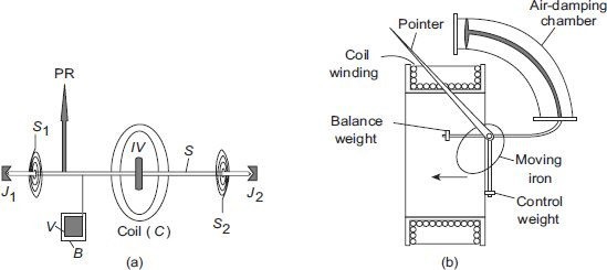
Repulsion-type Moving-Iron Instruments
In the type of repulsion, there are two blades inside the coil. One is fixed and the other is mobile. These also magnetize when the current passes through the coil and there is a repulsive force between the two blades that causes the movement of the dawn in motion.
The two most commonly used models of moving iron instruments are:
Radial Vane Type
In this type, the blades are radial iron bands. The strips are placed on the reel, as shown in Figure (a). The fixed pallet is attached to the reel and the mobile to the axis of the instrument. The pointer of the instrument is attached to the axis of the moving palette.
When the current flows through the coil, the generated magnetic field induces identical polarities in both the fixed sheet and the sheet. Therefore, even when the current in the coil is reciprocal (for the alternative measurement), there is always a repulsive force acting between the same poles of the blades and the mobiles. Therefore, the pointer deviation is always in the same direction, regardless of the polarity of the current in the coil. The amount of deviation depends on the repulsive force between the blades, which in turn depends on the amount of current flowing through the coil. In this way, the scale can be calibrated to directly read the current or voltage.
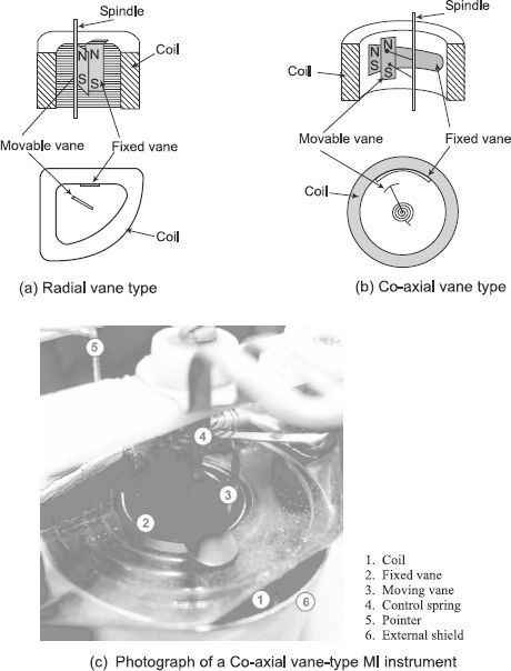
Co-axial Vane Type
In these types of instruments, the fixed and mobile vans are coaxial cylinder sections, as shown in Figure (b). The current in the coil magnetizes the two blades with a similar polarity. Therefore, the movable blade rotates along the axis of the spindle due to this repulsive force. Coaxial paddle instruments are moderately sensitive compared to the more sensitive radial pad instruments.
The deviation of moving iron instruments is proportional to the square of the current flowing in the coil. It is said that these instruments follow a square law response and that they have a non-uniform scale. The deviation is proportional to the square of the current, regardless of the polarity of the current in the coil, the deviation of an iron instrument in motion is in the same direction. Therefore, moving iron instruments can be used for continuous and alternate measurements.
Advantages of MI Instruments
- Robust development and moderately modest
- Suitable for estimating both dc and air conditioning
- Can withstand over-burden quickly
Disadvantages of MI Instruments
- As the diversion is corresponding to I 2, consequently the size of the instrument isn’t uniform. It is confined in the lower end and extended in the upper part.
- It is influenced by stray attractive fields.
- There is hysteresis blunder in the instrument. The hysteresis blunder might be limited by utilizing the vanes of nickel-iron composite.
- When utilized for estimating air conditioning the perusing might be influenced by variety of recurrence because of the adjustment in reactance of the loop, which has some inductance. With the expansion in recurrence iron loses and curl impedance increments.
- Since enormous measure of intensity is expended to supply I2R misfortune in the curl and attractive misfortunes in the vanes, it’s anything but a touchy instrument.
Electrodynamometer-Type Instruments
The electrometer is a transfer-type instrument. A transfer type instrument is an instrument that can be calibrated with a DC power source and then used without modifications to measure the AC current. This requires that the transfer type instruments have the same accuracy for DC and AC.
The electrodynamic instrument or dynamometer is a moving coil instrument, but the magnetic field in which the coil moves is provided by two fixed coils instead of permanent magnets. The schematic diagram of the electrodynamic instrument is shown in Figure 2.16 (a) and a practical meter in Figure 2.16 (b). It consists of two fixed coils, located symmetrically. It would have a pair in one direction during the middle of the cycle and an identical effect in the opposite direction during the other half of the cycle. However, if we reverse the flow direction each time the current is reversed through the voice coil, a unidirectional pair will be generated for both positive and negative cycle halves. In electrodynamic instruments, the field can be inverted simultaneously with the current in the voice coil if the fixed coil is connected in series with the voice coil.
Electrodynamic Ammeter
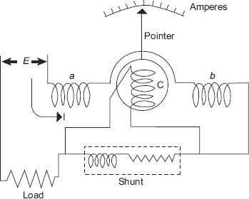
In an electrodynamic ammeter, the fixed and mobile coils are connected in series, as shown in Figure 2.17. A tap is connected through the voice coil to limit the current. The reactance-resistance ratio of the shunt and the voice coil is kept almost identical for the independence of the meter reading with the power frequency. Since the coil currents are equal, the deviation torque is proportional to the mean square value of the current. Thus, the scale is calibrated to read the effective value.
Electrodynamic Voltmeter
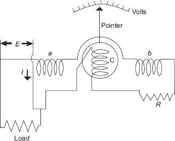
The electrodynamic instrument can be used as a voltmeter by connecting a large non-inductive resistance (R) of low temperature coefficient in series with the coil of the instrument, as shown in the figure.
Electrodynamic Wattmeter
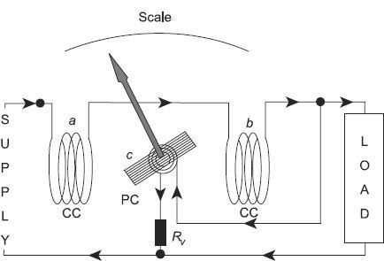
The electrodynamic wattmeter consists of two fixed coils “a” and “b” placed symmetrically one above the other and producing a uniform magnetic field. They are connected in series with the load and are called current coils (CC). The two fixed coils can be connected in series or in parallel to give two different nominal currents. The current coils carry the full charge current or a fraction of the full charge current. Therefore, the current in the current coils is proportional to the load current. The voice coil “c”, in series with a high non-inductive resistance Rv, is connected to the power supply. Therefore, the current flowing in the voice coil is proportional and substantially in phase with the supply voltage. The voice coil is also called a voltage coil or pressure coil (CP). The tension coil is transported on a pivoting shaft that carries the needle, the needle moves on a calibrated scale.
Two hair springs are used to provide the control torque and to carry the current in and out of the voice coil. The cushioning is provided by the friction of the air. The figure shows the basic arrangement of an electrodynamic wattmeter.
Electrostatic Instruments
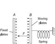
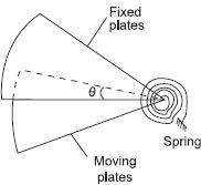
In electrostatic instruments, the deviation torque is produced by the action of an electric field in the charged conductors. These instruments are essentially voltmeters, but can be used with external components to measure current and power. Its most commonly used in the laboratory is the measurement of high voltages.
Induction-Type Instruments
Induction instruments are only used for AC measurements and can be used as ammeters, voltmeters or wattmeters. However, the principle of induction finds its widest application as a watt-hour or energy meter (for more details, see Chapter 8). In such instruments, the deviation torque occurs due to the reaction between the flux of an alternating magnet and the eddy currents induced by another flux.
Principle of Operation
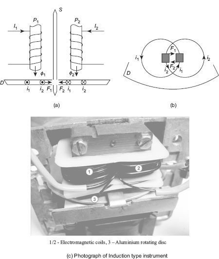
The operations of induction type instruments depend on the production of torque due to the interaction between a flow Φ1 (whose intensity depends on the current or voltage to be measured) and the eddy current induced in a disk or drum. another flow 2 (whose magnitude also depends on the current or voltage to be measured). Since the magnitude of the Foucault current also depends on the flow that produces it, the instantaneous value of the torque is proportional to the square of the current or voltage that is measured and the average torque value is proportional to the average square value of this current or this voltage.
Consider a thin disk of aluminum or copper D free to rotate around an axis passing through its center, as shown in Figure 2. The electromagnets P1 and P2 produce, respectively, alternative flows Φ1 and Φ2 that cut this disk. Consider any annular part of the disk around P1 with the center of the axis of Pl. This part will be limited by the flow Φ1 and will induce an alternation emf Φ1. Φ2 will induce an emf e2 that will further induce a Foucault current i2 in an annular part of the disk around Pl. This Foucault current i2 passes below the pole P1.
Suppose that the descending directions of the flows are positive, and suppose that at the given instant, 1 and 2 both increase. By applying Lenz’s law, we can find the direction of the induced currents i1 and i2 as shown in the figure
Electro-thermal Instruments
There are mainly two types of thermal instruments:
- Type of hot wire
- Thermocouple instrument
The movements of the hot wire and thermocouple meters use the effect of heating the current flowing in a resistor to cause the meter to deviate. Everyone uses this effect in a different way. Since their operation depends only on the heating effect of the current flow, they can be used to measure DC and AC currents of any frequency on a single scale.
Hot-wire Instrument
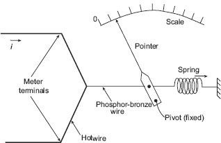
The movement deviation of the hot cable meter depends on the expansion of a high resistance cable caused by the heating effect of the cable itself as the current passes through it. A resistance cable is stretched between the two terminals of the meter, with a cable connected perpendicular to the center of the cable. A spring connected to the opposite end of the cable exerts a constant tension on the resistance wire. The current flow heats the cable, causing it to expand. This movement is transferred to the gauge indicator through the cable and a pivot. The figure shows the basic arrangement of a hot wire instrument.
Thermocouple-Type Instrument
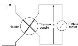
When two metals that have different work functions are placed together, a voltage is generated in the joint, which is almost proportional to the temperature of the joint. This union is called thermocouple. This principle is used to convert thermal energy into electrical energy at the junction of two conductors, as shown in the figure.
The heat in the joint is generated by the electric current flowing in the heating element, while the thermocouple generates a GEF through its output, which can be measured using a PMMC meter. The electromotive force produced is proportional to the temperature and, therefore, to the rms value of the current. As a result, the scale of the PMMC instrument can be calibrated to read the current flowing through the heater. The type of thermocouple instrument can be used for AC and DC applications. The most effective feature of a thermocouple instrument is that it can be used to measure current and very high frequency voltages. In fact, these instruments are very accurate well above a frequency of 50 MHz.
Rectifier-Type Instruments
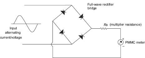
The basic arrangement of a rectifier type instrument that uses a full wave rectifier circuit is shown in the figure. If this instrument is used to measure an amount of AC, the AC signal is first converted to DC by the rectifier. Then, this continuous signal is measured by the PMMC counter. The multiplicative resistor Rs is used to limit the value of the current so as not to exceed the rated current of the PMMC counter.
These types of instruments are used for low intensity work where the voltage is low and the resistance is high.
Also further studies, read here: