
Why Maximum Power Transfer Theorem?
What is the maximum Power Transfer Theorem? In electrical engineering or any other field of science that involves the analysis of linear circuit design, sometimes the learner wants to learn new patterns and behaviors of the circuit over a period of time. This curiosity gives birth to new ideas and later those ideas reform themselves into a new shape, a method or a process or a new identity. Maximum power transfer theorem is also one such idea that prevailed because of the curiosity of the learner. Mortiz von Jacobi came up with the idea of finding the power that a circuit provide to the load. Thus following his idea, he later researched and published the Maximum power theorem in almost 1840. Till date it is also referred to as “Jacobi’s law”.
In any electrical circuitry system, source supply the voltage to the load. This voltage appears to be in the form of electrical energy. This electrical energy when reaches the load resistance, it is utilized by the load. Thus a conversion of energy takes place. This converted energy can then be utilized to perform any sort of work for which the load resistance is designed. As the law of conservation of energy takes place, energy is converted from one form into another. But the problem rises in the circuit. The total supplied energy is sometimes not equal to the total energy utilized. Some losses occur due to heating and the path used by electrical energy to flow. Thus the total power supplied by the source will not be available, as it is, at the load terminal. Thus a difference between drawing and delivering power do exist inside the circuit.
Also as we have studied earlier, the amount of power transferred from source to load resistance do have a relation with the resistance at load site. Simply stating, load resistance does have an effect on the power supplied. Therefore, maximum power transfer theorem comes in handy to deal such problems. It ensures all the necessary conditions to be maintained to transfer the power to the load with minimal loss.
Introduction to Maximum Power Transfer Theorem
The maximum power transfer theorem states that in a linear, bilateral direct-current circuitry network, to obtain maximum power from the source for the load, the value of load resistance should be equal to the equivalent resistance of the circuit network. In simple words, the load resistance should be equal to the Thevenin’s resistance of the circuit.
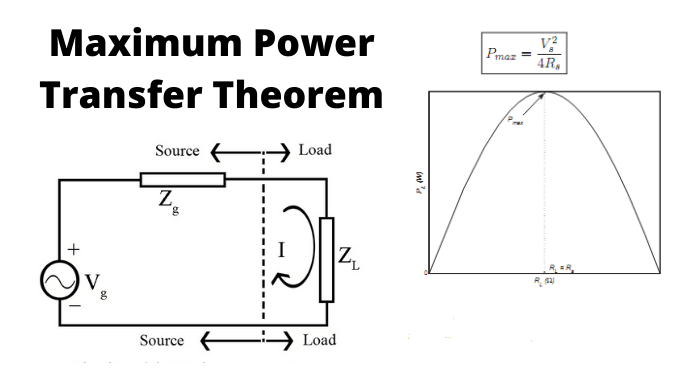
Thus for an independent current source, the parallel Thevenin’s resistance should be the same as the load resistance. Similarly, for an independent voltage source, the Thevenin’s resistance in series should be the equal to the load resistance.
In case of alternating-current voltage source, the maximum power for load is obtained, only if the load’s impedance’s value is equal to the complex conjugate of the source’s impedance.
Maximum Power Transfer Theorem Proof
Maximum power transfer theorem is quite different for both the AC and DC circuit. In DC circuit we primarily focus on the Thevenin’s resistance whereas in AC circuit our prime motive is to equate the load resistance and the circuit’s equivalent impedance. We will discuss both cases differently.
Maximum Power Transfer Theorem for DC Circuits
Analyzing below circuit, we see that this DC circuit is a two terminal network. The maximum power theorem is implemented by obtaining the expression of power absorbed by the load resistance. This can be done by simply using mesh or nodal analysis techniques and then deriving the power expression with respect to load resistance.
This procedure is quite complex and length but we can simplify it using Thevenin’s equivalent circuit as shown below.
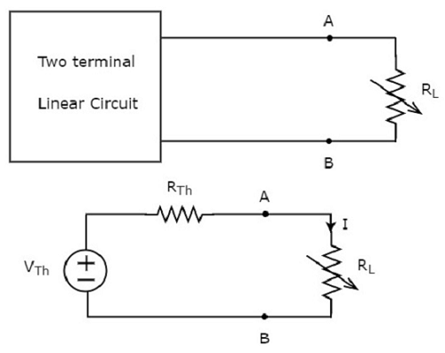
After comparing both the circuits, we conclude that the original two terminal circuit is replaced by thevenin’s equivalent circuit across the variable load resistance.
The current through the load resistance is given by ohm’s law as:
$$
\mathbf{I}_{\mathbf{L}}=\frac{\mathbf{V}_{\mathrm{TH}}}{\mathbf{R}_{\mathrm{TH}}+\mathbf{R}_{\mathrm{L}}}
$$
The power received by the load is
$$
\begin{gathered}
\mathbf{P}_{\mathbf{L}}=\mathbf{I}_{\mathrm{L}}^2 * \mathbf{R}_{\mathrm{L}} \\
=\left[\frac{\mathbf{V}_{\mathrm{TH}}}{\mathrm{R}_{\mathrm{TH}}+\mathrm{R}_{\mathrm{L}}}\right]^2 * \mathbf{R}_{\mathrm{L}}
\end{gathered}
$$
As the thevenin’s equivalent is a constant, thus from the expression, the power delivered to the load resistance depends entirely on the magnitude of load resistance by the source. Now, in order to find the value of load resistance, we apply laws of differentiation to load power and will equate it to zero as shown below
$$
\begin{gathered}
\frac{\mathrm{dP}\left(\mathbf{R}_{\mathrm{L}}\right)}{\mathrm{dR}_{\mathrm{L}}}=\mathbf{V}_{\mathrm{TH}}{ }^2 *\left[\frac{\left(\mathbf{R}_{\mathrm{TH}}+\mathbf{R}_{\mathrm{L}}\right)^2-2 \mathbf{R}_{\mathrm{L}} *\left(\mathbf{R}_{\mathrm{TH}}+\mathbf{R}_{\mathrm{L}}\right)}{\left(\mathbf{R}_{\mathrm{TH}}+\mathbf{R}_{\mathrm{L}}\right)^4}\right] \\
\left(\mathbf{R}_{\mathrm{TH}}+\mathbf{R}_{\mathrm{L}}\right)-2 \mathbf{R}_{\mathrm{L}}=0 \\
\mathbf{R}_{\mathrm{L}}=\mathbf{R}_{\mathrm{TH}}
\end{gathered}
$$
Thus this equation states the whole theory of maximum power transfer theorem. It shows that maximum transfer by the source occurs only when the load resistance is equal to the thevenin’s resistance of the linear circuit. Now we will substitute the value $\mathbf{R}_{\mathrm{TH}}=\mathbf{R}_{\mathrm{L}}$ in previous equation that is
$$
\mathrm{P}_{\mathrm{MAX}}=\left[\frac{V_{T H}}{R_{T H}+R_L}\right]^2 * \boldsymbol{R}_L
$$
Where $\mathbf{R}_{\mathbf{T H}}=\mathbf{R}_{\mathbf{L}}$ thus
$$
P_{\mathrm{MAX}}=\frac{\mathrm{V}_{\mathrm{TH}}{ }^2}{4 \mathrm{R}_{\mathrm{TH}}}
$$
Now the total power delivered from the source to the load resistance is given as
$$
\begin{gathered}
\mathbf{P}_{\mathrm{T}}=\mathrm{I}_{\mathrm{L}}{ }^2 *\left(\mathbf{R}_{\mathrm{TH}}+\mathbf{R}_{\mathrm{L}}\right) \\
\mathbf{P}_{\mathrm{T}}=2 * \mathrm{I}_{\mathrm{L}}{ }^2 \mathbf{R}_{\mathrm{L}}
\end{gathered}
$$
Hence this equation satisfies the maximum power theorem in which maximum power from the source is delivered only when the load resistance is equal to the equivalent resistance of the circuit or also called the thevenin’s resistance.
Power Transfer Efficiency
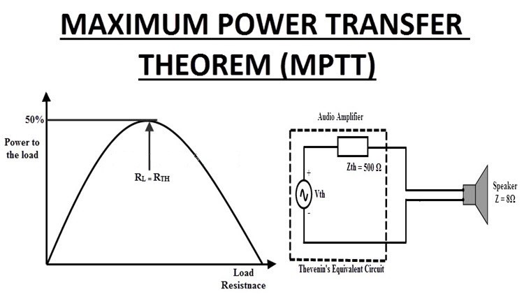
This theorem is the proper manifestation of maximum power transfer but the efficiency of this theorem in practical applications is not so good. One must not confuse himself with the maximum power transfer and maximum efficiency. Maximum power transferring does not refer to maximum efficiency. As most of the power is dissipated at the source hence the efficiency becomes low. The efficiency under such conditions is given as:
EFFICIENCY $=$ (OUTPUT/INPUT) $* 100$
$$
\begin{gathered}
=\frac{\mathrm{I}_{\mathbf{L}}{ }^2 \mathbf{R}_{\mathrm{L}}}{2 \mathrm{I}_{\mathrm{L}}{ }^2 \mathbf{R}_{\mathrm{L}}} * 100 \\
=50 \%
\end{gathered}
$$
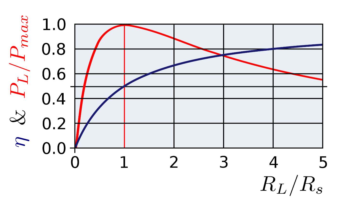
thus going by this formula, we come to know that half of the power is delivered to the load resistance while the other half is dissipated by the source itself along with the equivalent resistance.
Maximum Power Transfer Theorem For AC Circuits
In an active AC circuit, the basic condition for maximum power transfer theorem to hold is when the total impedance of the load is equivalent to the complex conjugate of the equivalent impedances of a given network.
After considering the above Thevenin’s equivalent circuit, the current flowing in the circuit is given by:
$$
I=\frac{V_{T H}}{\left(Z_{T H}+Z_L\right)}
$$
Where
$$
\begin{gathered}
\mathrm{z}_{\mathrm{L} .}=\mathbf{R}_{\mathrm{L}}+\mathrm{j \textrm {x } _ { \mathrm { L } }} \\
\mathrm{z}_{\mathrm{TH}}=\mathbf{R}_{\mathrm{TH}}+\mathrm{j} \mathrm{x}_{\mathrm{TH}}
\end{gathered}
$$
Therefore,
$$
\begin{gathered}
I=\frac{V_{T H}}{\left(\mathbf{R}_{\mathrm{L}}+\mathrm{jX}_{\mathrm{L}}+\mathbf{R}_{\mathrm{TH}}+\mathrm{jX} \mathrm{TH}^{\mathrm{TH}}\right)} \\
\mathrm{I}=\frac{\mathrm{V}_{\mathrm{TH}}}{\left(\mathbf{R}_{\mathrm{L}}+\mathbf{R}_{\mathrm{TH}}\right)+\mathrm{j}\left(\mathbf{X}_{\mathrm{L}}+\mathrm{X}_{\mathrm{TH}}\right)}
\end{gathered}
$$
The power delivered to the load resistance by the source is given as
$$
\begin{gathered}
\mathbf{P}_{\mathrm{L}}=\mathbf{I}^2 \mathbf{R}_{\mathrm{L}} \\
\mathbf{P}_{\mathrm{L}}=\frac{\mathbf{V}_{\mathrm{TH}}{ }^2 * \mathbf{R}_{\mathrm{L}}}{\left(\mathbf{R}_{\mathrm{L}}+\mathbf{R}_{\mathrm{TH}}\right)^2+\left(\mathbf{X}_{\mathrm{L}}+\mathbf{X}_{\mathrm{TH}}\right)^2}
\end{gathered}
$$
As we have done earlier, taking derivative and equating it with 0 , simplifying and we get
$$
\begin{gathered}
\mathrm{X}_{\mathrm{L}}+\mathrm{X}_{\mathrm{TH}}=0 \\
\mathrm{X}_{\mathrm{L}}=-\mathrm{X}_{\mathrm{TH}}
\end{gathered}
$$
Putting these results in above equation, we get
$$
\mathbf{P}_{\mathrm{L}}=\frac{\mathbf{V}_{\mathrm{TH}}{ }^2 * \mathbf{R}_{\mathbf{L}}}{\left(\mathbf{R}_{\mathrm{L}}+\mathbf{R}_{\mathrm{TH}}\right)^2}
$$
Again for maximum power transfer, derivation of above equation should be equal to zero thus we get
$$
\begin{gathered}
\left(\mathbf{R}_{\mathrm{TH}}+\mathbf{R}_{\mathrm{L}}\right)=2 \mathbf{R}_{\mathrm{L}} \\
\mathbf{R}_{\mathrm{L}}=\mathbf{R}_{\mathrm{TH}}
\end{gathered}
$$
Hence maximum power will be transferred from the source to the load if $\mathbf{R}_{\mathrm{L}}=\mathbf{R}_{\mathrm{TH}}$ and $\mathrm{X}_{\mathrm{L}}=-\mathrm{X}_{\mathrm{TH}}$ in an $\mathrm{AC}$ circuit. Thus it is proved from the derivation above that the load impedance is the complex conjugate of the equivalent impedance of the circuit. The maximum power transferred is given by
$$
\begin{gathered}
\mathbf{P}_{\text {MAX }}=\frac{V_{\mathrm{TH}}{ }^2}{4 R_{T H}} \text { or } \\
P_{\text {MAX }}=\frac{V_{\mathrm{TH}}{ }^2}{4 \mathbf{R}_{\mathrm{L}}}
\end{gathered}
$$
Steps for Implementing Maximum Power Transfer Theorem
In order to implement maximum power theorem in any circuit following steps should be considered
- The load resistance should be plucked away.
- In the circuit, using Thevenin’s or Norton’s theorem, the equivalent resistance of the circuit should be found.
- For the implementation of maximum power theorem this equivalent resistance should be equal to the load resistance that was plucked out initially.
- Use the formula for calculation of maximum power theorem.
Application of Maximum Power Transfer Theorem
When a linked source is present in a circuit, it makes the circuit active. So the maximum power transfer theorem is applicable for both active and passive elements. However, some common applications of this theorem are given below
- Maximum power transfer theorem can be implemented to linear circuitry networks and network systems having elements such as R, L, C & restrained linear sources.
- For proper function of this theorem, a variable load is required.
- Enormous sound systems are based on this process. The speaker’s resistance is matched with the resistance of amplifier’s. once their resistances match, they both are considered harmonized.
- In starter system of car, this theorem proves its worth. Power supplied on the starter rely mainly on the resistance of motor and battery’s resistance. When both are synchronous, highest power is transmitted to start the engine.
Also read here:
- what are the electrical properties of inductor?
-
How Many Types of Power Supplies are There?
-
Slip Rings and Its Use to Transmit Electrical Signal
-
Discuss diode: a non linear semiconductor device
-
What is the Plasma Physics?
-
How to test a diode? When diode is working and when it is not working?
-
How does the transformer work?
-
How to design voltage comparator using op-amp?
-
what are the small signal amplifiers and their applications?
-
what are the electrical properties of inductor?