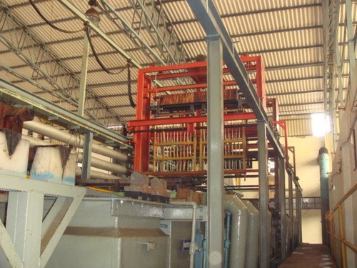
What is Nickel Coating Thickness Tester?
What is Nickel Coating Thickness Tester? Coating thickness gauges are of many types but we have decided to make non magnetic coating, ferrous base, digital thickness gauge because mostly coated material are non magnetic like paint, nickel, zinc, cadmium, powder coating etc. and all of these types of coating are mostly done over iron and steel. In Pakistan, such meters are not available easily in the market. Users have to import it which costs high.
Moreover, their maintenance is also a problem due to sensitive technology used in it. If we make such a tester, then not only we can sell our technology to industry but also it will help users of imported non magnetic coating, ferrous base, digital thickness gauge to keep its maintenance locally and it will be cheap. We will make this gauge mainly to test nickel plating thickness over different products since; it can save Pakistan two million dollars. Moreover, widely increasing demand of nickel plated products in whole world increase the importance of nickel coating thickness tester.
Nickel
Nickel-containing materials make major contributions to many aspects of modern life, but these often go unrecognized. The list is very long, and includes applications in buildings and infrastructure, chemical production, communications, energy supply, environmental protection, food preparation, water treatment and travel. All these areas rely, to some degree, on nickel’s unique combination of properties.
Nickel is found in the first transition series of elements in the periodic table, and this position gives rise to its metallurgical make-up:
- has a high melting point of 1453°C
- forms an adherent oxide film
- resists corrosion by alkalis
- is face-centered cubic, conferring ductility
- forms alloys readily, both as solute and solvent
- is ferromagnetic at room temperature
- is readily deposited by electroplating
- exhibits catalytic behavior
The future looks bright for nickel. Recent developments are expected to bring significant new nickel supplies to world markets within the next four to five years, and so the ready availability of these materials seems set to continue. The next century will pose many technological challenges. However they are tackled, nickel and nickel-containing materials are well-placed as cost-effective, long-lasting materials to be chosen for critical applications in tough environments and for enabling technological innovations to be exploited. Nickel will be contributing to our lives for many years to come.
The soft magnetic properties of nickel and its alloys are employed in electronic devices and for electromagnetic shielding of computers and communication equipment.
What is Electroplating?
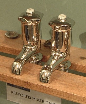
Nickel electroplating is extremely well-known and widely applied. The technique has long been used to provide both corrosion-resistant and decorative finishes, and is also used to create the substrate for chromium coatings. Plating on plastics has enjoyed considerable growth recently. The success of the process depends on suitable etching of the plastic to provide good adhesion to the first metallic deposit. Once this conducting layer is in place, the component can be electroplated in the normal way to produce a very durable, lightweight item. Nickel provides the corrosion resistance and lustrous appearance. Automobile trim, bathroom fittings and electronic connectors are just three ways this process is being exploited.
Nickel electroplating can also be used to make items by building up thick deposits on a substrate. The surface detail of the substrate is reproduced very faithfully on the deposit when the materials are separated This process is known as electroforming and is widely used to produce items as diverse as molds for pressing compact discs and security holograms, and screens for carpet printing.
Application of Nickel Plating:
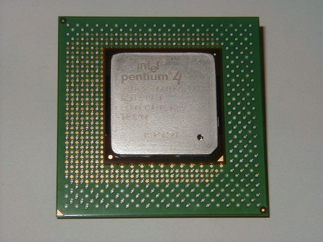
A major application of electroless nickel today is in computer hard discs. It forms an extremely uniform, smooth, stable, non-magnetic substrate for the magnetic recording layer, as well as providing corrosion protection for the underlying aluminum disc.
Automobile trim, bathroom fittings and electronic connectors are the commonly used employed electroplated items manufactured in industry.
Electroforming and is widely used to produce items as diverse as molds for pressing compact discs and security holograms, and screens for carpet printing.
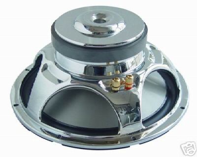
Nickel plating is also done over good quality speakers or amplifiers.
Nickel’s resistance to corrosion is one of its most valuable properties. The estimated annual cost of corrosion in the U.S.A. alone is $300 billion equivalent to 4% of gross national product. Far and away the largest use of nickel alloys is in the area of corrosion prevention.
Moreover as described before that manufacturing of coating thickness tester in Pakistan can save 2 million dollars to Pakistan.
Other Techniques to Measure Thickness of Nickel Coating:
Importance of nickel plating and its measurement is understandable but the question is why we use only nickel coating thickness tester for controlling the coating thickness of nickel over product in production line? Since other procedures are also present through which we can measure coating thickness.
There are other methods for measuring coating thickness, especially in automotive applications. These include the Coulometric, beta backscatter, and X-ray fluorescence techniques.
What is the micrometer?
Micrometers are sometimes used to check coating thickness. They have the advantage of measuring any coating/substrate combination but the disadvantage of requiring access to the bare substrate. The requirement to touch both the surface of the coating and the underside of the substrate can be limiting and they are often not sensitive enough to measure thin coatings.
Two measurements must be taken: one with the coating in place and the other without. The difference between the two readings, the height variation, is taken to be the coating thickness. On rough surfaces, micrometers measure coating thickness above the highest peak.
What is the Gravimetric?
By measuring the mass and area of the coating, thickness can be determined. The simplest method is to weigh the part before and after coating. Once the mass and area have been determined, the thickness is calculated using the following equation:
T = m x 10
A x d
where T is the thickness in micrometers, m is the mass of the coating in milligrams, A is the area tested in square centimeters, and d is the density in grams per cubic centimeter.
It is difficult to relate the mass of the coating to thickness when the substrate is rough or the coating uneven. Laboratories are best equipped to handle this time-consuming and often destructive method.
The Coulometric Method:
The Coulometric method has many important functions, such as measuring duplex nickel coatings in automotive applications. The technique involves determining the weight of an area of a metallic coating through localized anodic stripping of the coating, the calculating thickness based on mass per unit area.
Thickness measurement is made using an electrolysis cell, which is filled with an electrolyte specifically selected for stripping the particular coating. Constant current runs through the test cell to deplate the coating material, which serves as the anode. With current density and surface area being constant, coating thickness is proportional to the time it takes to strip the coating.
This method is particularly useful for measuring electrically conductive coatings on a conductive substrate.
The Beta Backscatter Method
The beta backscatter method begins when a test sample is exposed to beta particles from a beta-emitting isotope. A beam of beta particles is directed through an aperture onto the coated component, and a portion of these particles is backscattered from the coating through the aperture to penetrate a very thin window of a Geiger Muller (GM) tube. The gas of the GM tube ionizes, causing a momentary discharge across the tube electrodes. The discharge in the form of a pulse is counted by an electronic counter, which is then translated into coating thickness.
Materials of relatively low atomic number backscatter the beta particles at a significantly lower rate than materials of high atomic number. For example, a component with copper as a substrate and a gold coating 40 micro-inches thick, beta particles are scattered by both the substrate and the coating material. If coating thickness increases, the backscatter rate increases. The change in the rate of particles scattered is therefore a measure of coating thickness.
The technique is applicable when the atomic number of the coating and substrate differ by 20%. Applications include thickness measurement of gold, silver, and tin on electronic components, coatings on cutting tools, decorative plating on plumbing fixtures, and vapor-deposited coatings on electronic components, ceramics and glass. Other applications could include organic coatings such as oil or lubricant coatings over metals.
The X-ray fluorescence (XRF) Method:
X-ray fluorescence (XRF) is a versatile, non-contact, coating thickness measurement method for very thin multi-layer alloy coatings on small parts.
Measurement is performed by exposing the part to X-radiation. A collimator focuses the X-rays onto an exactly defined area of the test specimen. This X-radiation causes characteristic X-ray emission (fluorescence) from both the coating and the substrate materials. This emission is detected with an energy-dispersive detector.
Using the appropriate electronics, it is possible to register only the emission from the coating material or from the substrate. It is also possible to selectively detect a specific coating when intermediate layers are present. Common applications include printed circuit boards, electronic components, jewelry, and optical components.
All of these methods are difficult to adopt in a production line. Since these are time consuming, costly and require a separate setup. Hence, Coating thickness should be done through a portable gauge which should be easy to operate.
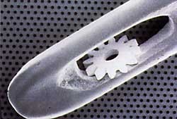
Destructive Tests:
One destructive technique is to cut the coated part in a cross section and measure the film thickness by viewing the cut microscopically. Another cross sectioning technique uses a scaled microscope to view a geometric incision through the dry-film coating. A special cutting tool is used to make a small, precise V-groove through the coating and into the substrate. Gages are available that come complete with cutting tips and illuminated scaled magnifier.
While the principles of this destructive method are easy to understand, there are opportunities for measuring error. It takes skill to prepare the sample and interpret the results. Adjusting the measurement reticule to a jagged or indistinct interface may create inaccuracy, particularly between different operators. This method is used when inexpensive, nondestructive methods are not possible, or as a way of confirming nondestructive results. ASTM D 4138 outlines a standard method for this measurement system.
Techniques to make Digital Coating Thickness Gauge:
There are different principles of electromagnetism through which a digital thickness gauge can be designed. These methods are explained below. Selection of one of these test methods depend upon required accuracy and type of measurement i.e. single coating or duplex coating, magnetic coating over magnetic substrate or non-magnetic coating over magnetic substrate.
Magnetic Pull-off
Magnetic pull-off gages use a permanent magnet, a calibrated spring, and a graduated scale. The attraction between the magnet and magnetic steel pulls the two together. As the coating thickness separating the two increases, it becomes easier to pull the magnet away. Coating thickness is determined by measuring this pull-off force. Thinner coatings will have stronger magnetic attraction while thicker films will have comparatively less magnetic attraction. Testing with magnetic gages is sensitive to surface roughness, curvature, substrate thickness, and the make up of the metal alloy.
Magnetic pull-off gages are rugged, simple, inexpensive, portable, and usually do not require any calibration adjustment. They are a good, low-cost alternative in situations where quality goals require only a few readings during production.
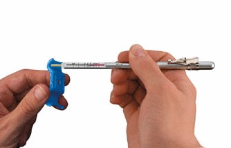
Pull-off gages are typically pencil-type or rollback dial models. Pencil-type models (PosiPen shown in Fig below) use a magnet that is mounted to a helical spring that works perpendicularly to the coated surface. Most pencil-type pull-off gages have large magnets and are designed to work in only one or two positions, which partially compensate for gravity. A more accurate version is available, which has a tiny, precise magnet to measure on small, hot, or hard-to-reach surfaces. A triple indicator ensures accurate measurements when the gage is pointed down, up, or horizontally with a tolerance of ±10%.
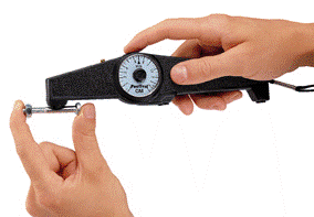
Rollback dial models are the most common form of magnetic pull-off gage. A magnet is attached to one end of a pivoting balanced arm and connected to a calibrated hairspring. By rotating the dial with a finger, the spring increases the force on the magnet and pulls it from the surface. These gages are easy to use and have a balanced arm that allows them to work in any position, independent of gravity. They are safe in explosive environments and are commonly used by painting contractors and small powder coating operations. Typical tolerance is ±5%.
The Magnetic Induction Method:
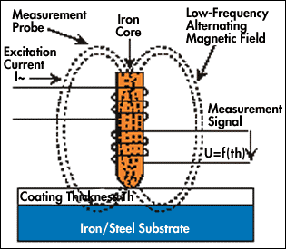
The magnetic induction method measures non-magnetic coatings over ferrous substrates and magnetic coatings over non-magnetic substrates. The process is direct, in that a probe is placed on the part to be measured. When the probe is positioned, the linear distance between the probe tip that contacts the surface and the base substrate is measured.
Inside the measurement probe is a coil that generates a changing magnetic field. When the probe is placed on the substrate, the magnetic flux density of this field is altered. The change in magnetic inductance is measured by a secondary coil. The output of the secondary coil is transferred to a microprocessor where it is viewed as a coating thickness measurement on a digital display.
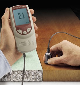
The magnetic induction method is quick and can be used with either a bench-top or hand-held coating thickness gage. It’s also non-destructive, relatively low-cost, easy to operate, accurate and repeatable, and measurements are instantaneous with a digital display.
Common applications for this test method include liquid or powder coatings, as well as plated finishes such as chrome, zinc, cadmium or phosphate over steel or iron substrates.
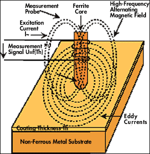
What is the Eddy Current Method?
The eddy-current method of coating thickness measurement measures non-conductive coatings on non-ferrous conductive substrates, non-ferrous conductive coatings on non-conductive substrates and some non-ferrous metal coatings on non-ferrous metals. It is very similar to the magnetic induction method and can even use many of the same probe designs. Advantages of the eddy-current method are also very similar to those of magnetic induction, including low cost, ease of operation, accuracy and repeatability and instantaneous measurement with a digital display.
Eddy-current coating thickness measurement uses a probe that also contains a coil. This probe/coil is driven by a high-frequency oscillator to generate an alternating high-frequency field. When this field is brought near a metallic conductor, eddy currents are generated in that conductive material, which results in the impedance change of the probe coil.
The distance between the probe coil and the conductive substrate material determines the amount of impedance change. Therefore, coating thickness is determined by the impedance change in the form of a digital reading.
Common applications for eddy-current coating thickness measurement include liquid or powder coating over aluminum and non-magnetic stainless steel as well as anodize over aluminum.
The Ultrasonic Pulse-Echo Technique
The ultrasonic pulse-echo technique of ultrasonic gauges is used to measure the thickness of coatings on nonmetal substrates (plastic, wood, etc.) without damaging the coating.
of coatings on nonmetallic substrates.
The probe of the instrument contains an ultrasonic transducer that sends a pulse through the coating. The pulse reflects back from the substrate to the transducer and is converted into a high frequency electrical signal. The echo waveform is digitized and analyzed to determine coating thickness. In some circumstances, individual layers in a multi-layer system can be measured.
Gauge Technology used in NON-MAGNETIC COATING, FERROUS BASE, DIGITAL THICKNESS GAUGE
The technique which we imply is little different from above mentioned technique however it uses permanent magnet as the source of magnetic field just like “Magnetic Pull-Off”. The magnetic field of this magnet varied in accordance with the distance between magnet and ferrous base on placing coating material of different thicknesses between them. This varied magnetic field is sensed and measured by a Hall Effect magnetic field sensor. This sensor linearly sense magnetic field and give analog voltage as an output. By calibrating the analog voltage according to the coating thickness by using nickel coating thickness standards we can measure nickel coating easily.
Also read here