Explain working of Programmable Logic Controller (PLC). Programmable logic controller is present in almost every industry. As the name suggests, we control digital and analog logics by embedding a program on hardware or module of the system. PLC comprises of different modules along with CPU for connecting software and hardware. Like Arduino board, it has multiple software for controlling the logics. Ladder language is used on software. Windows Control Centre or Wincc is used for displaying graphics which makes using PLC more efficient. PLC has many purposes in industries, such as:
- Controlling pressure of liquid
- Retaining certain temperature
- Controlling flow of liquid
- Controlling vibration of motors
Purpose of this research paper is to aware students and recent graduates about the demands of market. As PLC is a must for every industry so it has an endless spectrum. It’s a great way to initiate your career.
Introduction
Every factory, textile mills, oil refineries, in fact, all plants and industries are controlled by PLC. Engineers are further divided into three subcategories,
Electrical engineer: motors, fans, lights, Grid stations
Instrumentation Engineer: Level, flow, pressure, temperature, vibration
PLC and DCS Engineer:
Programmable logic control and Distributed control system.
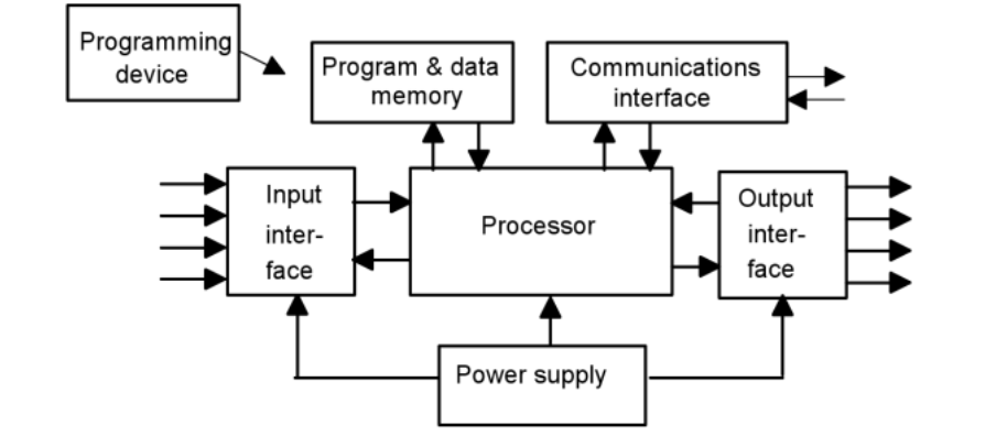
Multiple modules are connected to the controlling CPU. In industries and factories, hundreds of modules are connected to single CPU. Power supply is also required to power up module.
There are two types of input and outputs that are controlled:
- Digital inputs/outputs
- Analog inputs/outputs
EXAPLANATION:
When we talk about digital inputs/outputs we say something that is either turned on or tuned off, there’s no in-between. It consists of 0 and 1 values. A good example of digital outputs will be switches. When we turn on lights, they are either lit or not. What if we could control intensity of light? Now 0 and 1 values will not be enough to control the magnitude of light. Here we will use analog outputs to control the intensity. This might clarify the difference between Digital and analog in terms of PLC.
Examples of analog inputs/outputs include:
- Temperature
- Pressure of liquid
- Level of liquid
- Flow of liquid
- Vibration of motors
So, basically anything that has a percentage or magnitude is included in the pool of analog inputs/outputs. Inputs and outputs in PLC are taken standard to module. In other words, Signals received by module will be inputs and signals given out by module will be outputs. Let us breakdown the steps of above example:
- First user gives an input to its module to turn on the light.
- Module generates an output signal that turns on the light.
- Now another signal is received from the light as an indicator to tell user whether his task was successful or not.
Modules of PLC has multiple slots. You can assign any slot as input and output depending on the program that you have made on your software. If the analog input slot (assigned in software) is used as digital input slot, then the program will not run, and it will give an error.
USE OF PLC BY INDUCING STATISTICS:
In this research paper, I have told multiple times that PLC can control many productions of industries, now the question arises, why should it be controlled? One textile mill or cement mill has motor that consumes 1.5MW-6MW
Power. A regular house consumes around 6kW of power. Every day motor used in households consume 1.5kW power. Now when we talk about 6MW, it has a drastic change in comparison to regular motor. Regular motor’s vibration is known to anyone, and it promotes noise pollution in a tremendous manner. Just imagine the vibration caused by motors used in industries. To prevent this vibration and to control it we use PLC. PLC gives an indicator immediately when vibration passes a certain limit. It helps in preventing many accidents.
SOFTWARE OF PLC:
We have talked enough about the hardware of PLC, lets talk about software of PLC. Software of PLC is used to embed or burn the program in the memory of module. Different types of software are used. It depends upon the industry you’re working for. For example,
- Siemens
- ABB
- Mitsubishi
- Honey well
- Fisher Rosemount
- Omron
These are the organizations that provide different software for the use of PLC. Siemens is the most efficient, as it provides a software that helps all three subcategories of engineers, i.e., Electrical Engineer, Instrumentation engineer and PLC and DNS engineer
Siematic S7 is used for embedding logics on hardware. This software is provided by siemens.
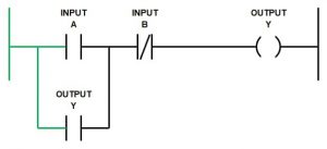
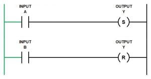
There are three types of languages used for PLC that includes:
- Ladder Language
- Statement List (STL)
- Control System Flowchart (CSF)
Ladder language is the most important among them because now-a-days, software are so advanced that they can convert ladder language into STL and CSF if conversion is required.
By using ladder language, everything is designed on Simatic S7, Desired program is run on software which is then uploaded on the CPU of module. But Simatic S7 just embeds a program on PLC, it doesn’t give us an indicator whether our task was successful or not. Let’s go back to our earlier example, suppose we have built a program that is used to turn on lights of industry. Now, how can user give input signal to either turn on or off lights? For this we use another software that is Wincc.
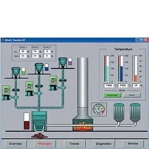
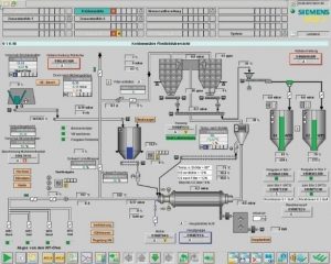
Windows Control Centre
Windows Control Centre or Wincc is used for generating graphics in your system. It is used to control the startup of your PLC. In Wincc we have a start button and stop button. Here we link the address of Wincc with Simatic S7, which then links the entire system.
Working of PLC
Summary of working of PLC in steps is listed as follows:
- Power up your module and connect it with CPU and Logics that is to be controlled.
- Design a program on Simatic S7 and burn it in the memory of CPU.
- Link the file of Simatic S7 with the address of Wincc, so that PLC can be controlled remotely.
- Start the program to give your input
- Receive the output signal from logics to verify whether your task was successful or not.
Also read here