Table of Contents
what is the difference between Mealy and Moore models?
what is the difference between Mealy and Moore models? Mealy and Moore models are the basic models of state machines. A state machine which uses only Entry Actions, so that its output depends on the state, is called a Moore model. A state machine which uses only Input Actions, so that the output depends on the state and also on inputs, is called a Mealy model. The models selected will influence a design but there are no general indications as to which model is better. Choice of a model depends on the application, execution means (for instance, hardware systems are usually best realized as Moore models) and personal preferences of a designer or programmer. In practice, mixed models are often used with several
action types. On an example we will show the consequences of using a specific model. As the example we have taken a Microwave Oven control presented already in another paper on our web site. This time we will make a very thorough analysis of the behavior exposing the specifics of the model used. The most general model of a sequential circuit has inputs, outputs and internal states. It is common to distinguish between two models of sequential circuits:
- Mealy model – The output is a function of both the present state and input.
- Moore model – The output is a function of the present state only.
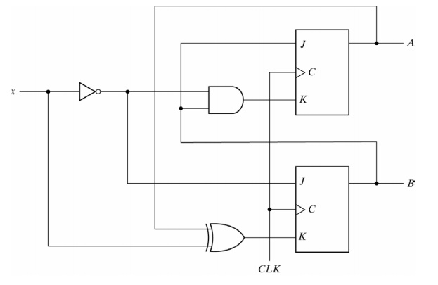
An example of a Mealy model is:
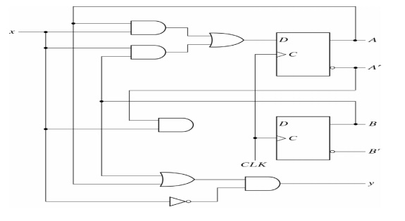
An example of a Moore model is:
In a Moore model, the outputs of the sequential circuit are synchronized with the clock because they depend on only flip-flop outputs that are synchronized with the clock.
In a Mealy model, the outputs may change if the inputs change during the clock cycle. To achieve synchronization, the inputs must be synchronized with the clock and the outputs must be sampled only during the clock edge.
STATE TABLE: The state table of a Mealy model sequential circuit must include an output section that is a function of both the present state and inputs. When the outputs are taken directly from flip-flops, the state table can exclude the output section because the outputs are already listed in the present column of the state table. In a general Moore model sequential circuit, there may be output section, but it will be a function of the present state only.
RESULT: In a Moore model the output of the sequential circuit are synchronized with the clock because they depend only flip-flop output that are synchronized with the clock. In a mealy model the output may change if the inputs change during the clock pulse period.
OUTPUT: Moreover, the output may have false values because of the delay encountered from the time that the inputs change and the time that the flip-flop output change. In order to synchronize a mealy type circuit, the input of the sequential circuit must be synchronize with the clock and the outputs must be sampled only during the clock-pulse transition.
Mealy’s Model:
A Mealy Machine is an FSM whose output depends on the present state as well as the present input.
It can be described by a 6 tuple (Q, ∑, O, δ, X, q0) where −
- Qis a finite set of states.
- ∑is a finite set of symbols called the input alphabet.
- Ois a finite set of symbols called the output alphabet.
- δis the input transition function where δ: Q × ∑ → Q
- Xis the output transition function where X: Q × ∑ → O
- q0is the initial state from where any input is processed (q0 ∈ Q).
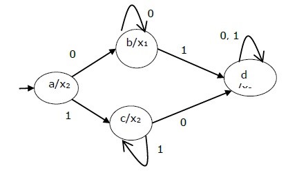
The state table of a Mealy Machine is shown below −
| Present state | Next state | |||
| input = 0 | input = 1 | |||
| State | Output | State | Output | |
| → a | b | x1 | c | x1 |
| B | b | x2 | d | x3 |
| C | d | x3 | c | x1 |
| D | d | x3 | d | x2 |
The state diagram of the above Mealy Machine is −
Moore’s Model:
Moore machine is an FSM whose outputs depend on only the present state.
A Moore machine can be described by a 6 tuple (Q, ∑, O, δ, X, q0) where −
- Qis a finite set of states.
- ∑is a finite set of symbols called the input alphabet.
- Ois a finite set of symbols called the output alphabet.
- δis the input transition function where δ: Q × ∑ → Q
- Xis the output transition function where X: Q → O
- q0is the initial state from where any input is processed (q0 ∈ Q).
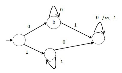
State table of a Moore Machine is shown below
| Present state | Next State | Output | |
| Input = 0 | Input = 1 | ||
| → a | b | c | x2 |
| B | b | d | x1 |
| C | c | d | x2 |
| d | d | d | x3 |
State diagram of the above Moore Machine
Also read here
https://eevibes.com/digital-logic-design/what-is-the-difference-between-fan-in-and-fan-out/