What is the Programmable Logic Array (PLA)?
PLA, a programmable logic array is a kind of logic device that can be map out to implement many kinds of combinational logic circuit. It contains a number of AND and OR gates which are connect together to give output or further merge with more gates or logic circuits. It is fixed architecture logic device with programmable AND and the programmable OR gate. Any kind of Boolean function in SOP form that can be implemented using PLA.
Explanation:
Programmable Logic Array or PLA has a map out AND array at input and map out the outputs at OR array. The number of AND gates in the programmable AND array are much less and the number of inputs of each OR gates equal to the number of AND gates. PLA and ROM both have the same idea but it does not provide full type of decoding variable and not generate all minterm in the ROM. PLA is a mixture of memory and logic. PLA is basic kind of map out logic device that can be used to rearrange the elements or setting of digital circuit. Components of PLA are map out AND gate matrix, input buffer and the OR gate matrix. PLA are the kind of PLD. PLA have a very slow speed as compared to the PAL. PLA have a ability to implement large number of function.
Components of PLA:
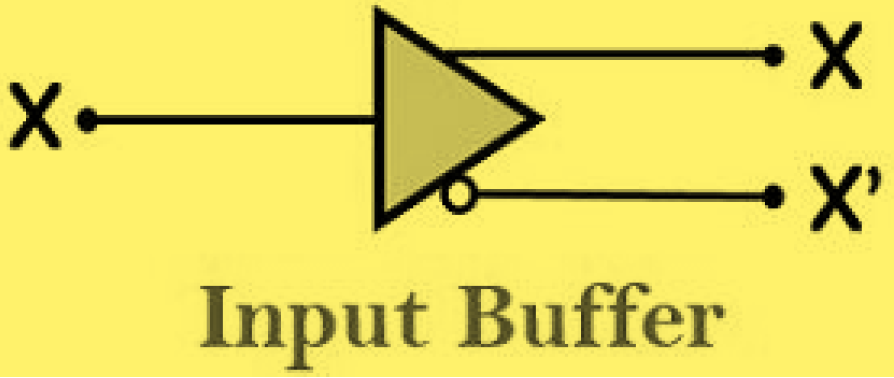
Input Buffer:
Mostly buffers at the input are used to overcome the load of the sources. The buffer create the complemented and non-complemented input as its output. Input buffers are mainly a combination of NOT gates.
No of input buffer = Total No of variables existing in Boolean expression.
Simplified form of above diagram:
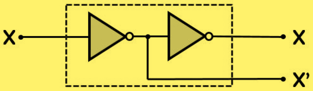
We can see that the above simplified diagram contain a two NOT gates. And the combination of two NOT gates fabricate both complement and no-complement input as well as output.so because at least in one case the input is complemented two times thus provide the initially provided input. However, in the other case the output is taken only after the first NOT gate.
AND Matrix:
We know that the AND logic gate only execute the multiplication. So, AND matrix to give always product terms as output. Mostly each AND gate in the circuits allow the product of the terms present in the complement and non-complement form at its inputs.
No of programmable AND gates = No of minterms in the expression (without repeat).
OR Matrix:
We know that the OR logic gate only execute the addition. Thus, the OR matrix always give the addition of the given input as the output.
No of programmable OR gate = No of functions in the expression.
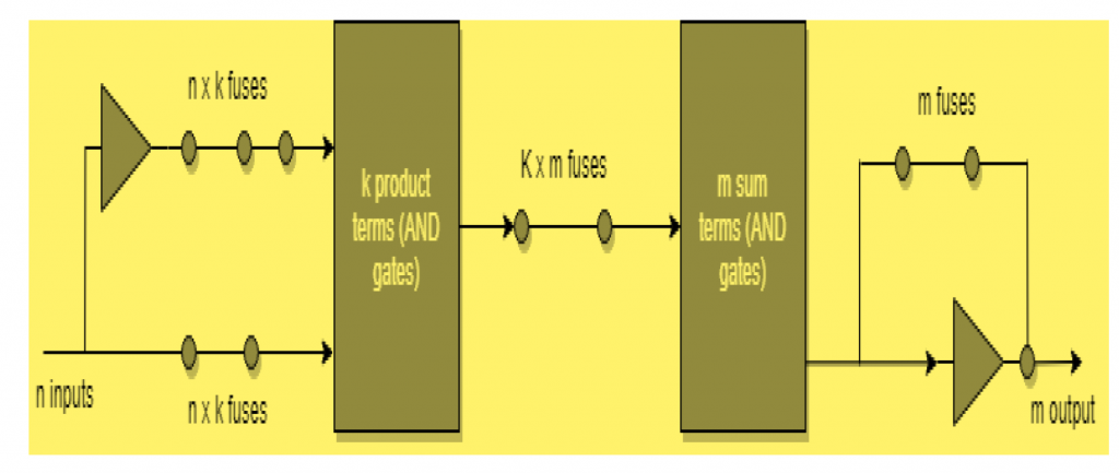
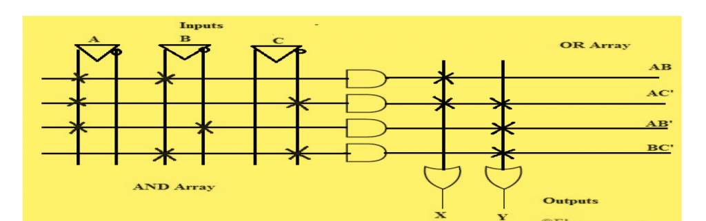
Basic Diagram of PLA:
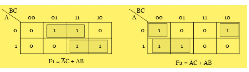
Truth Table will Provide help To Easily Understanding Function on no of Inputs:
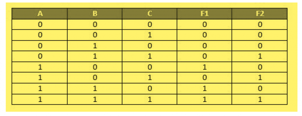
F1= AB’C’+ABC’
By simplifying get: F1= AB+AC’
F2= A’BC+AB’C+ABC
By simplifying get :F2=BC+AC
Advantages of PLA:
- No need in PLA for the moderate logic designing of random logic gate networks and even more moderate layout.
- Design study in PLA is much easy, and changing in designing is also much easy.
- Set up in PLA is much simple and easy as compared to the random logic gate, and much save the timing.
- Any kind of Boolean function in SOP form that can be implemented using PLA.
- PLA help in easy observation and correction of errors.
Disadvantages of PLA:
- PLAs and ROMs have very low speed as compared to the random- logic gate Networks.
- PLAs and ROMs have very high occupy chip areas as compared to the random-logic gate network.
- Setup of random-logic gate networks and the logic designing in PLA are much more dull and time-consuming.
- PLAs and ROMs are much expensive as compared to the random- logic gate network in term of volume production.
Application of PLA:
- PLA is use to provide the lead above data path.
- As a counter PLA are widely used.
- As a decoder PLA are also widely used.
- AS a BUS connection in programmed I/O PLA is mostly used.
Example of PLA
Following are the Boolean Expression to Implement with the help of programmable Logic Array (PLA).
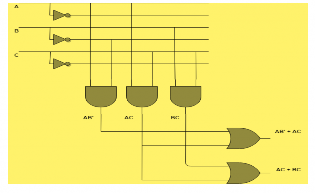
X=AB+AC’
Y=AB’+BC+AC’
Given are the above two Boolean function are in the form of SOP ( Sum of Products ) . X and Y are the product term in the above Boolean expression and one product term AC’ is similar in both the given equation. We are required the 4 AND gates or 2 programmable OR gate for generating the above two given equation. The equivalent PLA logic diagram as given below.
The AND gate which are programmable and the right hand side entry are normal as well as invert variable inputs. In the above given logic diagram of two equation the accessible input for each And gate are the A, A’, B, B’, C’ .Every AND gate create a single product term, the program is required.
All the products terms are available at the inputs of each OR gate. The programmable link on the logic gate can be represent with the symbol “ X “.
In this case the OR gate inputs are stable. Thus, the required product term are related with each OR gate inputs. AS conclusion, these gates will generate specific Boolean equations. “ . “ sign will indicates the permanent connections.
Example of PLA
In this example we are given a two Boolean functions F1 (A,B,C) = Σm( 1,3,6,7) and F2 (A,B,C) = Σm( 0,2,4,5). We solve these Boolean functions by using a PLA.
Here, both Boolean function are given in terms of the minterms. We implement the given Boolean function by using Karnaugh map.
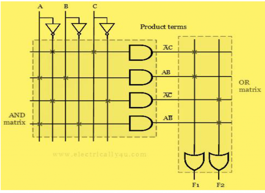
Given two obtained expression, the PLA circuit is perceive. Three inputs(A,B,C) and two outputs(F1,F2). Int the above expression there are four product terms and four AND gate array can be used. Only two OR gate that can be used to create the two Boolean functions.
Diagram of given Boolean function after realization:
Also read here