SMT assembly looks linear when it is shown as a factory flow: print solder paste, place components, reflow the board, inspect the result, and test the assembly. On a real production floor, those steps behave more like one shared process window. A paste deposit that is slightly high can turn into bridging after reflow. A package that shifts during placement may still look close enough before the oven but fail AOI afterward. A reflow profile that works on a simple board may not heat a dense assembly evenly enough.
That is why a useful SMT assembly process discussion should not stop at the names of the machines. The practical question is what each stage controls, what evidence it produces, and what defects can escape if the earlier stages are treated as isolated tasks. For a hardware team, NPI engineer, or sourcing manager, understanding that chain helps prevent a common problem: blaming final inspection for defects that were already created at the stencil, placement program, footprint, panel design, or reflow setup.
This guide follows the SMT assembly process from solder paste printing through final inspection. It focuses on production controls, defect containment, and the records that make a build repeatable.
SMT Assembly Starts With the Released Build Package
The first SMT process step happens before a board reaches the printer. The assembler needs a controlled build package: fabrication data, BOM, approved vendor list if applicable, pick-and-place file, assembly drawing, polarity notes, no-stuff list, test requirements, stencil file, panel drawing, and any special handling instructions.
This is not administrative overhead. It is the input that determines whether the line can build the same product twice. A footprint mismatch, missing polarity mark, unclear alternate component, or incomplete centroid file can create defects that look like assembly errors but actually started as documentation problems. First article inspection is much more useful when the build package is stable enough to compare against.
For prototypes, the package may still be evolving. For production, revision control matters more. If a BOM substitute changes package height, terminal plating, thermal mass, or moisture sensitivity, the SMT process may need a new review. If a PCB revision changes fiducials, panel rails, copper balance, or test access, the placement, inspection, and test programs may need updates as well.
Solder Paste Printing Sets the First Process Window
Solder paste printing is often the most important SMT step because it meters the solder volume before any component is placed. Reflow can melt the alloy, but it cannot fix a missing deposit, a bridged fine-pitch pattern, or paste that was placed off the pad.
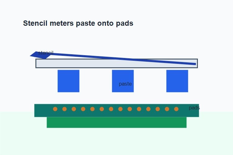
The stencil controls paste volume, not simply pad coverage. Fine-pitch ICs, QFNs, LGAs, BGAs, small passives, and thermal pads often need aperture strategies that differ from the copper pad shape. A thermal pad under a QFN, for example, may need segmented paste openings to reduce floating, solder beading, or voiding risk. The exact aperture design depends on the component, stencil thickness, pad geometry, solder paste, finish, and assembler rules.
Key printing controls usually include stencil alignment, stencil condition, paste storage and handling, squeegee pressure, print speed, separation speed, underside cleaning, support tooling, and board flatness. On thin boards, large panels, or assemblies with uneven support, board deflection can change paste height from one region to another.
Solder paste inspection gives the team an early process signal. SPI can show paste volume, area, height, offset, and bridging tendency before the board reaches placement. It does not prove final solder joint quality by itself, but it can catch print problems while the cause is still close to the process step that created them.
Placement Turns the Printed Pattern Into a Buildable Assembly
Once the board is printed, placement accuracy becomes the next control point. The pick-and-place program depends on accurate centroid data, package libraries, fiducial recognition, nozzle selection, feeder setup, placement force, and component orientation.
Many placement problems are easy to underestimate because the board may still look acceptable before reflow. A small passive can sit slightly off-center and then tombstone when wetting forces become uneven. A connector can shift just enough to create a weak joint. A polarized device can be placed correctly in the machine program but incorrectly in production if the component orientation in the reel or library is wrong.
First article checks should verify polarity, pin-one orientation, package match, placement offset, component height conflicts, missing or extra parts, and any special notes on the assembly drawing. For dense boards, it is also worth checking whether the placement sequence creates movement in previously placed parts or causes tall parts to block nozzles, cameras, or inspection angles.
The placement stage is also where design-for-assembly decisions become visible. Components placed too close together may be possible to mount but difficult to inspect or rework. Connectors near the board edge may need panel support. Bottom-terminated parts may need X-ray planning before production starts. SMT assembly is easier to stabilize when these constraints are reviewed before layout release.
Placement and Reflow Have to Be Tuned Together
Reflow soldering creates the metallurgical solder joints,but it is not an independent rescue step. It works with the solder volume, placement accuracy, component finish, pad geometry, board thermal behavior, and paste chemistry that entered the oven.

A reflow profile should be validated on the actual assembly, not assumed from a similar job. A board with heavy copper, large connectors, shields, BGAs, or dense local copper can heat differently from a simpler prototype. A profile that is too aggressive can stress components or laminate. A profile that is too weak can leave poor wetting, opens, or head-in-pillow risk on warped packages.
The useful evidence is not just the oven recipe. It is the measured profile on the board, with thermocouples placed at meaningful locations. The process should account for the solder paste supplier’s guidance, component limits, board construction, thermal mass, and any customer requirements. For mixed-technology builds, secondary soldering operations also need attention because the SMT side may see additional heating or handling later.
Reflow problems are often diagnosed by looking backward. Bridging may point to excess paste or placement offset. Opens may point to insufficient paste, package coplanarity, board warpage, or thermal imbalance. Voiding may involve paste volume, outgassing path, pad design, or profile behavior. The profile is part of the evidence, but it is rarely the only variable.
Cleaning and Post-Reflow Handling Are Process Decisions
After reflow, the assembly may move into cleaning, no-clean residue review, depaneling, touch-up, conformal coating preparation, or secondary assembly. These steps should be part of the process plan, not afterthoughts.
Flux residue risk depends on flux chemistry, board geometry, voltage, impedance, environment, coating requirements, and customer acceptance criteria. A no-clean process may be appropriate for many products, but the residue still has to be compatible with the design and environment. High-impedance sensor inputs, high-voltage spacing, conformal coating, and humid service conditions can change the risk assessment.
Handling after reflow also matters. A board can pass reflow and then be damaged by poor depaneling, fixture removal, connector handling, or uncontrolled rework. If the assembly has fine-pitch connectors, ceramic components, large BGAs, or thin laminate, mechanical handling should be treated as a controlled process step.
Inspection Is Layered Because Defects Are Different
Final inspection is not one method. It is a layered strategy that depends on the defect model. AOI, X-ray, manual inspection, ICT, flying probe, and functional test each see a different part of the assembly.
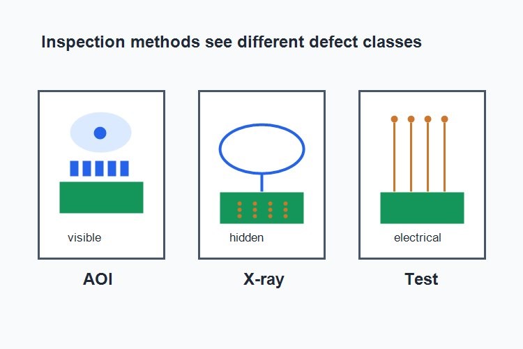
AOI is strong for visible placement and workmanship issues: missing parts, wrong polarity, skew, tombstoning, visible solder bridges, and many solder fillet defects. It depends on lighting, component libraries, camera access, and trained review of false calls. It does not prove electrical performance, and it cannot fully evaluate hidden solder joints.
X-ray inspection is used when the defect is not visible from the surface. BGAs, QFNs, LGAs, bottom-terminated components, hidden bridges, voids, and some insufficient-solder conditions may need X-ray or AXI. X-ray still needs acceptance criteria and trained interpretation. It does not replace electrical test or functional validation.
Electrical testing closes a different gap. Flying probe and ICT can find opens, shorts, some wrong values, and selected assembly faults when the design provides access. Functional test verifies product behavior under defined conditions. None of these tests prove every possible field condition unless the fault model, coverage, limits, and validation evidence support that claim.
What Each SMT Stage Should Leave Behind
The strongest SMT process is not just the one that produces good boards today. It is the one that leaves enough evidence to diagnose drift tomorrow.
| SMT stage | Main control point | Typical evidence | Defect classes contained |
| Build package review | Revision alignment, BOM clarity, placement data, assembly notes | DFM log, released BOM, assembly drawing, centroid file | Wrong parts, polarity errors, undocumented deviations |
| Solder paste printing | Paste volume, aperture strategy, board support, alignment | Stencil revision, SPI data, print setup records | Bridges, insufficient solder, paste offset, solder beads |
| Placement | Package library, nozzle setup, feeder loading, placement accuracy | First article report, placement program, feeder setup | Skew, tombstoning risk, wrong orientation, missing parts |
| Reflow | Board-level thermal profile and solder wetting behavior | Measured profile, thermocouple map, oven program | Opens, poor wetting, head-in-pillow risk, thermal stress |
| AOI and visual review | Visible placement and solder workmanship | AOI report, review images, defect trends | Missing parts, polarity, visible bridges, tombstoning |
| X-ray or AXI | Hidden-joint and internal solder features | X-ray images, inspection criteria, disposition records | BGA/QFN defects, hidden bridges, voiding concerns |
| Electrical and functional test | Circuit-level and product-level behavior | Test limits, logs, coverage notes, fixture revision | Opens, shorts, wrong values, firmware/configuration issues |
This evidence does not need to be excessive for every build. A simple prototype and a regulated production assembly will not carry the same documentation burden. The point is to match the records to the product risk, production volume, and customer requirements.
Defect Data Should Feed Back Into the Process
The strongest SMT teams do not treat inspection as a final sorting station. They use inspection data to decide which upstream control needs attention. A solder bridge on one fine-pitch component may point to paste volume, stencil design, placement offset, board support, or reflow behavior. The right corrective action depends on the pattern, not only the defect name.
Good defect data is specific. Record the reference designator, package type, feeder or reel lot where relevant, stencil area, board location, panel position, reflow lane or zone concern, inspection image, and disposition.
If several defects cluster in one panel corner, board support or print separation may be involved. If they cluster around one footprint, the land pattern or aperture design may need review. If they appear after a component lot change, solderability, coplanarity, moisture sensitivity, or terminal finish should be checked.
This is also where overcorrection can create new problems. Reducing paste to address bridging may increase opens on the same component family. Raising thermal energy to improve wetting may stress moisture-sensitive parts or create warpage risk. Increasing AOI sensitivity may catch more marginal features but can slow production with false calls. Corrective action should follow the evidence trail: define the suspected mechanism, change one controlled variable when practical, run a contained build, and compare results against the original defect pattern.
For production work, the useful metric is not just whether the current lot passed. The useful question is whether the process has enough margin to stay stable across component lots, paste age, stencil wear, fixture condition, operator shifts, and ordinary board-to-board variation. SMT process control becomes much more practical when defect data is used to maintain that margin instead of explaining failures after the fact.
Prototype SMT and Production SMT Are Not the Same Exercise
A prototype SMT build is often designed to learn quickly. The team may accept temporary workarounds, partial test coverage, or manual inspection while the design is still moving. That can be reasonable, as long as nobody mistakes a successful prototype build for a stable production process.
Production SMT requires tighter control of revision status, component sourcing, stencil ownership, feeder setup, first article release, inspection criteria, test limits, and change control. A prototype may pass because a skilled technician managed the difficult parts manually. A production line needs the design and process to be repeatable without heroic attention.
The transition point is where many assembly problems appear. If the first prototypes were hand touched, manually reworked, or built on temporary tooling, the team should identify which steps need to be converted into controlled production operations. That may include a new stencil, revised panelization, added fiducials, more test access, X-ray criteria, or a fixture for functional test.
Standards Help Define the Boundary, Not the Whole Process
IPC standards are useful when they are applied with the right scope. J-STD-001 is commonly used for soldered electrical and electronic assembly requirements. IPC-A-610 is commonly used for electronic assembly acceptability. IPC-7525 is commonly routed for stencil design guidance, and IPC-7530 is commonly routed for temperature profiling in soldering processes. The current revision, product class, customer drawing, and contract requirements should be verified for the actual build.
The important point is that a standard reference does not replace product-specific engineering. A board can be inspected against an acceptability standard and still need additional functional test, environmental validation, cleanliness control, or customer-specific criteria. Likewise, an SMT defect can be unacceptable for a high-reliability product even when a different product class might treat the same observation differently.
In a professional RFQ or build package, standards language should be specific. Name the standard family, revision if known, class if applicable, acceptance criteria, and any customer exceptions. Avoid vague wording that leaves the assembler guessing whether the requirement is workmanship, soldering process control, cleanliness, documentation, or final performance.
Practical SMT Process Checklist Before Release
Before releasing a design into SMT assembly, review these items with the assembler:
- Confirm the BOM, centroid file, assembly drawing, stencil file, and PCB revision match.
- Review fine-pitch, QFN, LGA, BGA, small passive, connector, and high-thermal-mass footprints.
- Confirm stencil strategy for paste volume, thermal pads, fine-pitch apertures, and special components.
- Check fiducials, tooling holes, panel rails, board support, and depaneling method.
- Verify polarity markings are visible and unambiguous after placement.
- Confirm moisture-sensitive component handling requirements from the component documentation.
- Decide which defects SPI, AOI, X-ray, ICT, flying probe, and functional test are expected to catch.
- Define rework limits, retest requirements, and change-control triggers.
- Confirm which IPC or customer acceptance criteria apply and where product-specific requirements override default assumptions.
This checklist is not a substitute for a full DFM or DFT review. It is a practical way to keep the SMT process discussion focused on items that create recurring defects.
For an RFQ or production handoff, the same checklist should become a conversation with the assembler rather than a file dump. Ask which inputs are missing, which assumptions will affect stencil design, which packages need special inspection, and which tests require layout access. If the assembler has to infer polarity, cleaning requirements, fixture access, panel support, or acceptance criteria, the process already contains avoidable risk. The best time to remove that risk is before the stencil is ordered and before the first article build is scheduled.
This matters even more when a design is being transferred from one assembler to another. A stable build at one factory may depend on tooling, solder paste, oven behavior, inspection libraries, or operator knowledge that is not visible in the Gerber files. A clean transfer should include process records, known defect history, approved substitutions, test limits, rework notes, and any open engineering issues from previous builds.
Conclusion
The SMT assembly process is a chain of controlled decisions. Solder paste printing establishes the first measurable process window. Placement turns that printed pattern into a physical assembly, while reflow converts the setup into finished solder joints. Inspection and testing then verify different parts of the defect model. When these stages are managed as one connected process, defects are easier to prevent, trace, and correct.
A reliable SMT assembly service should also leave clear production evidence behind, including DFM notes, stencil revisions, SPI results, placement settings, measured reflow profiles, AOI and X-ray records, test logs, and change history. These records are what turn one successful build into a repeatable manufacturing process. Without them, final inspection becomes little more than defect sorting rather than a true quality control system.
FAQ
What is the basic SMT assembly process?
The basic SMT assembly process is solder paste printing, component placement, reflow soldering, inspection, and test. A production build also needs build-package review, stencil control, first article inspection, rework rules, and process records.
Why is solder paste printing so important in SMT assembly?
Solder paste printing controls the solder volume and location before components are placed. If the paste is missing, excessive, offset, or bridged, later steps may expose the defect but usually cannot remove the root cause.
Does AOI catch all SMT assembly defects?
No. AOI is useful for visible placement and solder defects, but it cannot fully evaluate hidden joints or prove electrical function. BGAs, QFNs, and other bottom-terminated packages may need X-ray, and the finished product may still need electrical or functional test.
When should X-ray inspection be used after SMT assembly?
X-ray inspection is useful when the solder joint or defect is hidden from normal optical inspection. Common examples include BGA solder joints, QFN thermal pads, hidden bridges, internal voiding concerns, and some insufficient-solder conditions.
Is a reflow oven recipe enough for process control?
No. The oven recipe is only the machine setting. Process control needs a measured profile on the actual board and carrier, with thermocouples placed at meaningful locations and limits checked against paste, component, material, and customer requirements.
How does SMT assembly differ between prototype and production?
Prototype SMT may tolerate temporary workarounds while the design is still changing. Production SMT needs controlled revisions, stable stencil and placement programs, inspection criteria, test limits, and change control so the build can be repeated.