Transformer Equivalent Circuit
How to Draw the Transformer Equivalent Circuit? In order to draw the equivalent circuit of the transformer, all real loses that occur in it must be considered. The terms that are used for drawing the equivalent circuit of the transformer are:
- Copper Losses
- Eddy Current Losses
- Hysteresis Losses
- Leakage Flux
Copper Losses in Transformer
Copper losses are calculated as I2R. They are produced because of the resistive heating losses in primary and secondary windings of the transformers. Copper losses are directly proportional to the square of currents in the windings.
Eddy Current Losses
These losses are produced because of the resistive heating in the core of transformer. These losses are directly proportional to the square of the voltages that are applied to the transformers.
Hysteresis Losses
During each half cycle, magnetic domains are rearranged in the core of the transformer which actually cause the hysteresis losses. These are complex and are non-linear function of the applied voltages to the transformers.
Leakage Flux
Leakage flux is the flux that escape the core and passes only through one of the transformer windings. They are ΦLP and ΦLS. Self induction is caused because of these escaped fluxes in the primary and secondary coils. The effects of this inductances must be accounted for.
The Exact Equivalent Circuit of a Transformer
By taking into account all the major imperfections it s possible to design an equivalent circuit of a transformer. Every major imperfection is considered in turn and the effect is introduced in the transformer model.
Coper losses are easy to be modeled. Since they are the resistive losses in the primary and secondary coils, so they are modeled by introducing a resistor RP in primary circuit and RS in secondary circuit.
The voltage produced in the primary winding because of leakage flux ΦLP is given as:
eLP(t)=NP(d ΦLP/dt)
and the voltage produced in the secondary windings because of leakage flux is given as:
eLS(t)=NS(d ΦLS/dt)
Because air makes up a significant amount of the leakage flux path and because air has a constant reluctance that is significantly higher than the core reluctance, the flux ΦLP and flux ΦLS are directly proportional to the primary circuit current and secondary current, iP and iS respectively.
$$
\begin{aligned}
&\phi_{\mathrm{LP}}=\left(\mathscr{P} N_{P}\right) i_{P} \\
&\phi_{\mathrm{LS}}=\left(\mathscr{P} N_{S}\right) i_{S}
\end{aligned}
$$
where $\mathscr{P}=$ permeance of flux path
$N_{P}=$ number of turns on primary coil
$N_{S}=$ number of turns on secondary coil
By substitution and simplification, we will get the following equations :
$$
\begin{aligned}
&e_{\mathrm{LP}}(t)=N_{P} \frac{d}{d t}\left(\mathscr{P} N_{P}\right) i_{P}=N_{P}^{2} \mathscr{P P} \frac{d i_{P}}{d t} \\
&e_{\mathrm{LS}}(t)=N_{S} \frac{d}{d t}\left(\mathscr{P} N_{S}\right) i_{S}=N_{S}^{2} \mathscr{P P} \frac{d i_{S}}{d t}
\end{aligned}
$$
The constants in these equations can be lumped together. Then
$$
\begin{aligned}
&e_{\mathrm{LP}}(t)=L_{P} \frac{d i_{P}}{d t} \\
&e_{\mathrm{LS}}(t)=L_{S} \frac{d i_{S}}{d t}
\end{aligned}
$$
where $L_{P}=N_{P}^{2 \mathscr{P}}$ is the self-inductance of the primary coil and $L_{S}=N_{S}^{2 \mathscr{P}}$ is the self-inductance of the secondary coil. Therefore, the leakage flux will be modeled by primary and secondary inductors.
How to Model the Effects of Core Excitation of Transformer?
It is a little tricky. As we know that the magnetization current im is directly proportional to the voltage applied to the core and it lags by 90 degree to the applied voltages. By connecting a reactance Xm across the primary voltage source this magnetization current can be modeled.
A resistance Rc connected across the primary voltage source can be used to mimic the core-loss current ih+e , which is a current that is proportional to the voltage applied to the core and is in phase with the applied voltage. The inductance Xm and the resistance Rc are, at best, approximations of the actual excitation effects (keep in mind that both of these currents are truly nonlinear).
The equivalent circuits that results with these assumptions is shown below:
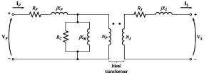
The components of the excitation branch are positioned inside the primary resistance Rp and the primary inductance Lp, as can be seen.
Voltage applied to the core=input voltages-internal voltages drops of the windings
The model displayed above is not used much although it is an accurate model. For drawing an equivalent practical circuit of transformer it is necessary to model it at a single voltage level.
Therefore we can refer the equivalent circuit either on its primary side or on its secondary side as shown below:

Also read here: