Introduction
What are the Three Phase Transformers? In today’s world almost all the distributive and generative systems are three-phase AC systems. It is the need of the hour to understand how transformers are used since three phase systems play a vital roe in modern times.
There are two possible ways to construct transformers for three phase circuits:
- In first approach you can simply take a three phase transformer and then connect it in three-phase bank.
- Another approach is to design a three-phase transformer with three separate wires wound around a common core.
These possible arrangements for the transformers are shown below:
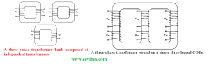
Single three-phase transformers are preferably constructed today as they are lighter in weight, smaller in size, cost effective and quite efficient. Previously, three separate transformers were used for the construction of three phase transformers. But the advantage of this approach was that in case of trouble in any unit, it was easy to be replaced independently.
But still this does not outweigh the advantages of single three-phase transformer for many applications.
Three-Phase Transformers Connections
The three-phase transformers that actually consists of three transformers either separate or combined on a same core. Their primaries and secondaries can be connected either in wye (Y) or delta (Δ) connection form.
There are four possible connections for three-phase transformer using these arrangements.
- Wye-wye (Y-Y)
- Wye-delta (Y-Δ)
- Delta-wye (Δ-Y)
- Delta-delta(Δ-Δ)
For the analysis of three-phase transformer it is necessary to analyze a single transformer in the bank. The behavior of a single transformer is exactly like a single phase transformer.
All the parameters calculations like: impedance, efficiency, voltage regulation all are done as per the single phase basis. This uses the same techniques that have been developed for a single-phase transformer.
Now lets see what are the advantages and disadvantages of three phase transformer connections are.
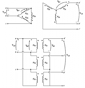
Y-Y (wye-wye) Connection
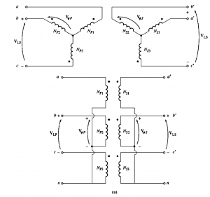
In this connection, the primary voltage are given by VΦP=VLP/√3. The relation between primary and secondary voltages are given using the turn ration (N).
The relation between phase voltage on the secondary is associated with the line voltage on the secondary. The overall voltages of the transformer is given as:
\begin{equation}
\frac{V_{\mathrm{LP}}}{V_{\mathrm{LS}}}=\frac{\sqrt{3} V_{\phi P}}{\sqrt{3} V_{\phi S}}=a \quad \mathrm{Y}-\mathrm{Y}
\end{equation}
Problems of Y-Y connections:
There are two main problems of Y-Y connection or configuration:
- If the unbalanced load is present at the transformer circuit, then the voltages on the secondary of the transformers become unbalanced.
- Can Produce very large third harmonic voltages.
The voltages in any phase will be 1200 apart from the voltages in any other phase if a three-phase set of voltages is supplied to a Y-Y transistor. However, each of the three phases’ third-harmonic components will coincide with the other two phases.
Moreover, each cycle in the basic has three counterparts in the third harmonic frequency. In every song, there are some third-harmonic components. These components add up to form transformer due to the core’s nonlinearity.
It will result in very large third harmonic voltage component on the top of 50 or 60 HZ fundamental voltages.
How to remove the problems of unbalancing load and third harmonics produced in wye-wye connections of the three-phase Transformers?
These above mentioned problems of unbalancing and large harmonics produced can be solved using the following techniques.
- Grounding the Neutrals of Transformers Solidly
- Connecting a tertiary winding in Δ to Transformer Bank
Lets discuss each of them individually.
Grounding the Neutrals of Transformers Solidly
Ground the neutrals of the transformers firmly, paying specific attention to the neutral of the primary winding. Instead of building up high voltages, this connection enables the additive third-harmonic components to generate a current in the neutral. A return path for any current imbalances in the load is also provided by the neutral.
Connecting a tertiary winding in Δ to Transformer Bank
Add a third (tertiary) winding that is connected to the transformer bank at position Δ . The third-harmonic components of the voltage in the Δ-connected winding will add up if a third Δ-connected winding is added to the transformer, resulting in a circular current flow within the winding.
The third harmonic components of voltage are suppressed by this in a similar way the transformer neutrals are grounded.
Although they are frequently utilized to supply lights and auxiliary power inside the substation where the transformer is located, the Δ-connected tertiary windings do not even need to be brought out of the transformer box. The tertiary windings are typically made with about one-third the power rating of the two main windings because they must be big enough to accommodate the circulating currents.
If we are planning to use Y-Y connection these it is required to use any of these techniques.
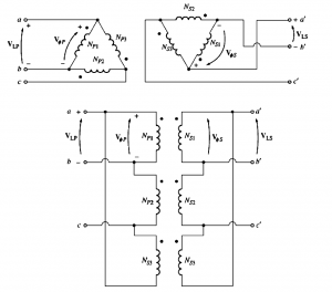
Wye-Delta Connation
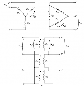
In this connection, the relation between primary line voltages and primary phase voltages is given as VLP=/√3VΦP. While the relation between secondary line voltages and secondary phase voltage is given as:
VLS= VΦS
For each phase, the voltage ration is given by:
VΦP / VΦS =a
Hence the overall relation between the line voltages on the primary and secondary side of the bank is given as:
\begin{equation}
\begin{aligned}
&\frac{V_{\mathrm{LP}}}{V_{\mathrm{LS}}}=\frac{\sqrt{3} V_{\phi P}}{V_{\phi S}} \\
&\frac{V_{\mathrm{LP}}}{V_{\mathrm{LS}}}=\sqrt{3} a \quad \mathrm{Y}-\Delta
\end{aligned}
\end{equation}
This connection has no issue with the third-harmonic of the voltages as on the Δ side they are consumed in the circulating current. Also wye-Δ connection is more stable with respect to the unbalanced loads. As Δ is redistributes if any imbalance occurs.
Delta-Wye (Δ-Y) Connection
In this connection the primary line voltages are equal to primary phase voltages given as:
VLP= VΦP
And the secondary voltages are related by:
VLS= =√3VΦS
Hence, line to line voltage ratio for delta-wye connection is given by:
\begin{equation}
\begin{aligned}
&\frac{V_{\mathrm{LP}}}{V_{\mathrm{LS}}}=\frac{V_{\phi P}}{\sqrt{3} V_{\phi S}} \\
&\frac{V_{\mathrm{LP}}}{V_{\mathrm{LS}}}=\frac{\sqrt{3}}{a} \quad \Delta-\mathrm{Y}
\end{aligned}
\end{equation}
Both wye-delta and delta-wye configurations have the same advantages.
Delta-Delta (Δ-Δ) Connection
This connection has the advantage of no phase shift and there is no problem of unbalanced loads and third-harmonics associated with them. The line voltages on the primary side are related to phase voltages by this formula:
VLP= VΦP
Similarly, voltages on the secondary side are related by:
VLS= VΦS
Hence the relation between primary and the secondary line voltages is given as:
\begin{equation}
\frac{V_{\mathrm{LP}}}{V_{\mathrm{LS}}}=\frac{V_{\phi P}}{V_{\phi S}}=a \quad \Delta-\Delta
\end{equation}
Also read here