Design a Raspberry Pi project for toggling a switch
How to Design a Raspberry Pi Project for Toggling a Switch?
Raspberry Pi:
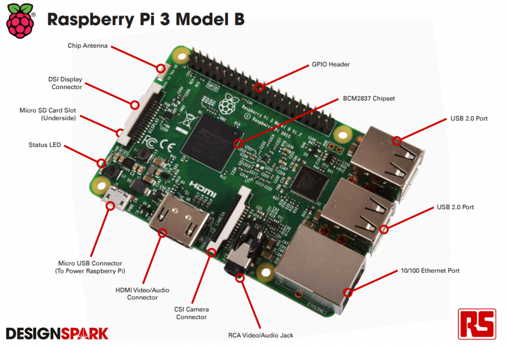
The Raspberry Pi is a low-cost, computer-sized computer that connects to a computer monitor or TV, and uses a standard keyboard and mouse. It is a small, efficient tool that enables people of all ages to scan a computer and learn to type in languages such as Scratch and Python.
It can do everything you would expect a desktop computer to do, from browsing the internet and playing high-definition video, creating spreadsheets, word processing, and playing games.
The Raspberry Pi has a 700MHz single-core processor and a Video Core IV GPU. Playing with a small 256MB of RAM, the Pi is a modest piece. It uses an SD card in its operating system and data storage. Keep in mind that the main purpose of this chip is to enable a cheap computer with a basic level of performance, especially for education.
Models:
These are the Raspberry Pi models currently available:
- Pi 3 Model B
- Pi 2 Model B
- Pi Zero
- Pi Zero W
- Pi 1 Model B + and A +
Model A / A + has one USB port, Model B has two ports, and Model B +, Raspberry Pi 2 Model B, and Raspberry Pi 3 Model B have four ports. This can be used to connect multiple USB 2.0 devices. Additional USB devices such as mice, keyboards, network adapters, and external storage can be connected via a USB hub.
Working:
The standard SD card installed on the board acts as a Raspberry Pi hard drive. It is powered by USB and video output can be connected to a traditional RCA TV set, a modern monitor, or a TV using an HDMI port. This gives you all the basic computer skills. It also uses an extremely low power of 3 watts.
GPIO:
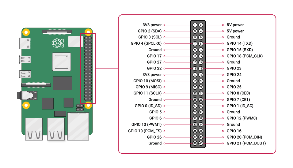
A powerful feature of the Raspberry Pi is the GPIO anchor line (general-purpose input / output) pins at the top edge of the board. The 40-pin GPIO header is available on all current Raspberry Pi boards (not included in Pi Zero and Pi Zero W). Prior to Pi 1 Model B + (2014), boards had a short 26-pin header.
Any GPIO pins can be selected (on the software) as an input or output pin and used for various purposes.
-
PROGRAMMING IN RASPBERRY PI:
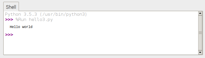
One of the ways to edit in raspberry pi is to use “python”. Python is a powerful and professional language, which is good for beginners and very fun to learn. A very simple introduction to Python by Thonny, the Python3 development environment. Because one of Python’s main goals was to be read and stick to simple English, its “hello world” program is as simple as possible.
- Open Thonny Python IDE from the main menu.
- Enter the following code:
print(“Hello world”)
- Save the file as hello3.py.
- Click the Run button.
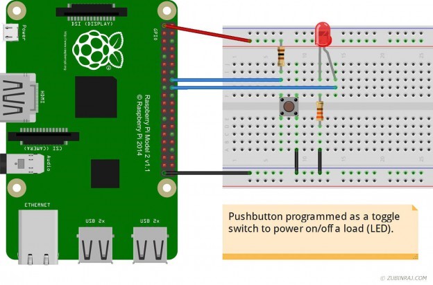
- Raspberry Pi – Button As a Digital Toggle Switch:
The ability to directly control GPIO pins (standard plug-ins) is one of the reasons why the Raspberry Pi is so popular among the hobbyists and educators.
In this project, it will show the status of the button, determine if it is pressed or not and then, turn off or off the LED.
Components:
- Raspberri Pi 2 Model B (40 pin) with Raspbian OS
- Breadboard
- Connectors
- LED 5mm
- Push Button
- Resistors – R1 (330 ohm) & R2 (1K ohm)
This setup uses GPIO 23 (pin # 16) and GPIO 24 (pin # 18), but you can use any GPIO pins for this purpose.
- GPIO 23 (pin # 16) – Used as an input to read button status
- GPIO 24 (pin # 18) – Used as output to switch the LED on and off
- + 3.3V (pin # 1) – Attached to power rail on breadboard
- GND (pin # 9) – Attached to the ground rail on the breadboard
- R1 – Connected between LED and ground
- R2 – Connected between 3.3V power rail and button
Program:
You need a system to tie these instruments together; read the status of a button and send signals to illuminate the LED.
First we need to familiarize some terms which are:
- digitalWrite () – used to send output to the GPIO pin. The first parameter is the pin number. The second parameter determines whether the pin should be set to HIGH or LOW (can only take 2 regions).
- digitalRead () – used to read GPIO pin status. Only the parameter transferred to the PIN number. Output can be HIGH or HOME and can be considered as below:
if ( digitalRead (pin) ) // this means the button is not pressed or is open
{ }
if ( !digitalRead (pin) ) // this means the button is pressed or is closed
{ }
The next part is how to change. This is done by remembering the previous status of the button and if it changes, find out if you turn off or off the LED.
TOGGLE:
# include <wiringPi.h>
void ledOn(int pin)
{
digitalWrite (pin, HIGH);
}
void ledOff(int pin)
{
digitalWrite (pin, LOW);
}
int main (void)
{
const int BUTTON = 23; // GPIO 23, pin #16
const int LED = 24; // GPIO 24, pin #18
// initial setup
wiringPiSetupGpio();
// set the pin mode as either INPUT or OUTPUT
pinMode(LED, OUTPUT);
pinMode(BUTTON, INPUT);
int state = 0;
// initial state
int press = 0;
int prev = 0;
int val;
while (1)
{
if (!digitalRead(BUTTON))
press = 1; // pressed
else
press = 0; // not pressed
// at every button press, toggle the state
if ((press == 1) && (press != prev))
state = !state;
// store prev value
prev = press;
if (state == 1)
ledOn(LED);
else
ledOff(LED);
// add delay to avoid the bounce
delay (75);
}
return 0;
}
CONCLUSION:
Here, we saw how we can learn to install a button and record the output to illuminate the LED using the GPIO Raspberry Pi pins. Once we have mastered these basics well, then the same information can be used to drive other loads such as transfers, vehicles etc.
Also read here