Introduction
Explain RC Coupled Transistor Amplifier. The RC coupled transistor amplifier is one of the most popular types of amplifier circuits. It is widely used in a variety of applications such as audio amplifiers, radio transmitters and receivers. The circuit consists of two transistors, a resistor and a capacitor connected in series. The first transistor acts as an input stage and the second transistor acts as an output stage.
The input signal is applied to the base of the first transistor. This transistor amplifies the signal and applies it to the base of the second transistor. The second transistor amplifies the signal further and applies it to the load resistance. The capacitor couples the two stages together and allows only the ac component of the signal to be amplified. The resistor provides DC biasing to the transistors.
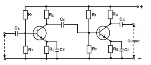
The circuit shown in Figure 1 is a common emitter RC coupled amplifier using NPN transistors.
Also check:
what are the small signal amplifiers and their applications?
The input signal is applied to the base of Q1 via R1. Q1 amplifies the signal and applies it to the base of Q2 via C1. Q2 amplifies the signal further and applies it to the load resistance, RL. C2 couples the two stages together and allows only the ac component of the signal to be amplified. R2 provides DC biasing to the transistors.
The circuit shown in Figure 2 is a common collector RC coupled amplifier using PNP transistors.
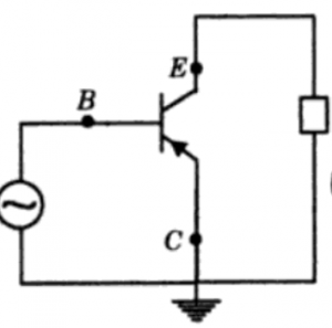
The input signal is applied to the base of Q1 via R1. Q1 amplifies the signal and applies it to the base of Q2 via C1. Q2 amplifies the signal further and applies it to the load resistance, RL. C2 couples the two stages together and allows only the ac component of the signal to be amplified. R2 provides DC biasing to the transistors.
The main advantage of the RC coupled amplifier is that it has a relatively high input impedance and a low output impedance. This makes it ideal for use in applications where it is necessary to match the impedance of the amplifier to the impedance of the load. The RC coupled amplifier is also relatively simple to construct and is therefore a popular choice for many applications.
Voltage Gain of RC Coupled Amplifier
The voltage gain of an RC coupled amplifier is determined by the ratio of the collector resistor to the base resistor. The higher the ratio, the higher the voltage gain. For example, if the collector resistor is 10 times the value of the base resistor, the voltage gain will be 10.
Bandwidth of RC Coupled Amplifier
The bandwidth of a RC coupled amplifier is determined by the value of the capacitors used in the circuit. The larger the capacitor, the wider the bandwidth. The bandwidth is also affected by the resistor values in the circuit. Higher resistor values will result in a narrower bandwidth. The bandwidth can also be increased by adding additional capacitors to the circuit.
How to Calculate Bandwidth of RC Circuit?
The bandwidth of an RC circuit is determined by the time constant, which is the product of the resistance and capacitance. The time constant is a measure of the time it takes for the voltage to ramp up or down in response to a change in current. The larger the time constant, the slower the voltage will change in response to a change in current, and the smaller the bandwidth. The time constant is also a measure of the frequency at which the voltage will start to roll off. The higher the time constant, the lower the frequency at which the voltage will start to roll off.
To calculate the bandwidth of an RC circuit, you need to know the value of the resistance and capacitance, and the time constant. The time constant is the product of the resistance and capacitance.
The bandwidth of an RC circuit is given by:
Bandwidth = 1 / (2 * pi * time constant)
where:
pi is 3.14159…
time constant is the product of the resistance and capacitance.
Example for Calculating Bandwidth
For example, if the resistance is 10 ohms and the capacitance is 0.1 Farads, then the time constant would be 1 second. The bandwidth would be:
Bandwidth = 1 / (2 * pi * 1)
Bandwidth = 1 / (6.283)
Bandwidth = 0.16 Hz
This means that the voltage will start to roll off at frequencies below 0.16 Hz.
If you know the bandwidth, you can calculate the time constant. The time constant is the inverse of the bandwidth.
Time constant = 1 / bandwidth
For example, if the bandwidth is 0.1 Hz, then the time constant would be:
Time constant = 1 / 0.1
Time constant = 10 seconds
This means that it would take 10 seconds for the voltage to ramp up or down in response to a change in current.
If you know the time constant, you can calculate the resistance and capacitance. The resistance is given by:
Resistance = time constant / capacitance
Also read here