Introduction to SCR
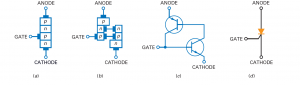
What are the Applications of SCR? A silicon controlled rectifier is a 4 layered PNPN device which has three terminals: Anode (A), Cathode (K) and Gate (G). The basic structure and the schematic diagram of SCR is shown in the figure below:
SCR is one of the most widely used thyristor. It is used for switching large currents. That’s why it is used in many applications like
- Motor Controlling
- Microwave Ovens
- Air Conditioners (AC)
- Induction Heaters
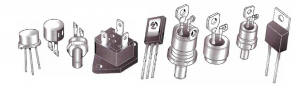
Typical SCR packages are shown in the figure below. Some of the Thyristors are also found in the similar packages.
Equivalent Circuit of SCR
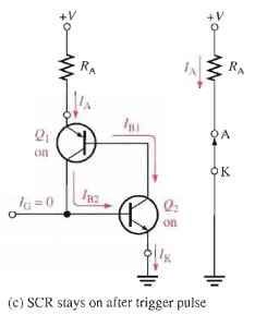
As mentioned earlier, SCR is a 4-layered device PNPN. The upper three layers (PNP) are considered as QI transistor (Since transistor is a three-layered device). The lower layer (NPN) is named as Q2. Hence you can simply say that two transistors are connected together sharing two layers between them. This is shown in Figure 1 (c). This arrangement is just like a 4-layer diode except with the gate terminal.
How to Turn On the SCR?
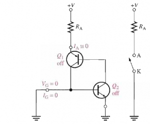
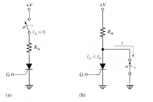
When we set the gate current IG=0, then it will be in OFF state and there will exist a very high resistance between Anode and Cathode terminals which can be approximated by an open circuit between them. This is shown in the figure below:
When we apply the triggering current IG at the gate terminal then if anode to cathode voltages are positive SCR will be turned ON. Since both transistors (pnp and npn) are turned ON. For understanding this conduction, consider the phenomenon shown in the figure below:
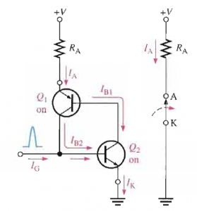
When gate pulse is applied it also acts as IB2 of Q2. This IB2 provides path to IB1 into the collector of Q2. Thus Q1 is turned ON. Once Q1 is turned ON, its collector current will be added to the base of Q2 so that Q2 remains in the conduction state even after the gate pulse is removed. Hence in this way, Q2 provides the conduction path to Q1 and Q1 sustains the conduction in Q2. This is actually a regenerative procedure. This keeps the device in latching state (ON state) once it is triggered ON using a pulse.
In this state, we can say there is a very low resistance existing between anode and cathode terminals that is usually approximated by the closed switch as shown in figure 5.
How to Turn OFF the SCR?
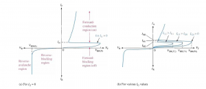
Once we turn ON the SCR with the gate pulse, it will remain in the conduction state. In order to turn it OFF, the anode current must go below the holding current which is shown in the characteristics curves of SCR.
There are two main methods to turn OFF the SCR:
- Forced Commutation
- Anode Current Interruption
Anode Current Interruption
In this technique we can interrupt the anode current either by series or parallel switching as shown in the figure below. In series current interruption a switch is added as shown in part (a) of figure 7 If the switch is opened it will make current equal to zero thus turning OFF the SCR. In the parallel current interruption we just provide an alternate low resistive path to the anode current hence reducing anode current bellow holding current Ih. This will take away energy from both transistors ultimately.
Forced Commutation
In forced commutation we actually provide the current opposite to the direction of anode current which will ultimately reduce the SCR current below the holding current The circuit for this configuration is shown in the figure below:
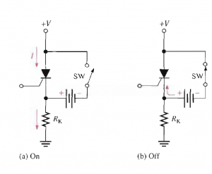
It consists of a battery and a transistor in parallel with the SCR. As long as we want to keep SCR in conduction state (ON state), we keep this switch open. Once we want to turn OFF the SCR, we will close that switch which will actually connect SCR with the battery. That will result in current through SCR but in the opposite direction to the anode current. This will reduce SCR current below the holding current that will ultimately turn OFF the SCR.
Applications of SCR
SCR is usually used for power controlling and switching purposes. Lets see what are the different applications of SCR.
On-Off Control of Current
SCR can be used for controlling the current provided to load. The following figure shows the diagram of this application of thyristor.
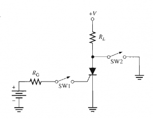
By the momentary closure of switch S1 current is permitted to the load and by the momentary closure of the switch S2 current is removed from the load. When SCR is OFF and we close the switch S1, then gate pulse is applied to SCR which will turn it ON as anode to cathode voltages are positive and hence it will provide energy to load. SCR will remain in conduction state even after the switch S1 is opened now as long as anode current remains equal or greater than the holding current Ih.
When switch S2 is closed, the current is shunted around the SCR and it takes the low resistive path thus reducing the anode current below the holding current Ih.
In this way SCR will be turned OFF and load current will be reduced to zero.
Half-wave power control
One of the applications of SCR is to control the power delivered to lamps, dimmers and electric heaters. The following figure shows the half-wave variable resistor which is actually phase-controlled.
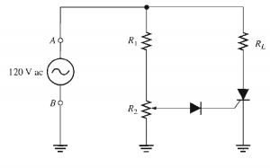
Here it can be noticed that 120V ac source is connected, RL is the load resistor, R1 is the current limiting resistor and while R2 is the potentiometer that actually sets the triggering point of SCR.
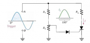
By adjusting the value of R2 we can set SCR to trigger at any point of positive half cycle between 0 to 90 degree. When the triggering takes place at the beginning of positive half-cycle (approximately at 0 degree) then it conducts for whole positive cycle (180 degree) and maximum power is delivered to the load as depicted in the figure below.
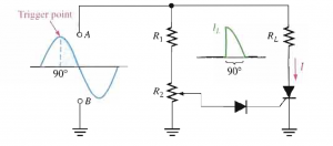
When triggering takes place at the positive peak of positive half cycle (approximately at 90 degree) then it will conduct for (90 degree to 180 degree) and less power is delivered to the load.
Hence by controlling the value of R2 we can control the power delivered to the load. For the negative half-cycle of input wave form, SCR is turned off. The purpose of diode is to prevent the negative current at the gate of SCR.
Over-Voltage Protection Circuit
The over-voltage protection circuit which is also called a “crowbar” circuit in a dc power supply is shown in the below diagram.
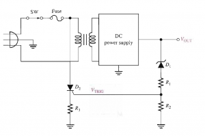
Here we have used Zener diode Z1 and voltage divider circuit for monitoring the output voltages from DC power supply. Zener voltages set the upper limit of voltages provided by this power supply. If the voltages exceeds then Zener starts conduction and voltage divider circuit produces triggering current for SCR which will turn it ON. It can be noticed that SCR is connected to the line voltages where the fuse is present. The current flowing through SCR causes the fuse to blow. In this way line voltages are disconnected from power supply.
Also read here:
- How Tunnel diode works?
- What are the switching circuits of diode? Examples and Problems
- How to test a diode? When diode is working and when it is not working?
- How zener diode is used for voltage and line regulation?
- What is the varactor diode and how does it work?
- what is the difference between drift and diffusion current of a diode?
- What is the light emitting diode (LED)? How does it work?
- What is the barrier potential of PN junction diode ?