Introduction to Arduino Based Color Mixer
How to Design an Arduino based Color Mixer? Basically, we generated some colors that we can see with some twists like changing colors in some mixing form. For this purpose, we use an Arduino UNO board (model R3). We sketched the program for color mixing project in Arduino computer application and then after powering Arduino board with DC supply we connected Arduino board with laptop using data cable and uploaded code to Arduino.
Beside this, we used some basic electronic components including Arduino board, variable rotatory potentiometers, breadboard, RGB LED, resistors.
We used Arduino board to program a color mixer by using breadboard and some electronic components and sketching code in computer application.
Components Required
- Breadboard
- Arduino board (using Arduino Uno)
- Male-male jumpers (about 15)
- Potentiometers (using 5K pots)
- Resistors-3 (330 ohms)
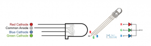
- Red-Green-Blue Led (or RGB Module)
- Arduino IDE computer application
Procedure
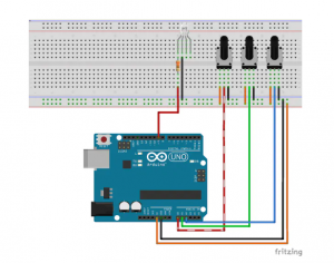
First of all, we brought all components mentioned above. We sketched Arduino program for color mixing project. We setup Arduino board by giving it DC supply. We used breadboard for constructing circuit.
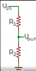
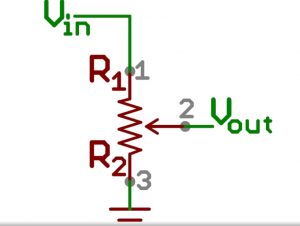
In the given diagram pot is used as voltage divider circuit whereas, Arduino pin is Vout.
The variable amount of voltage (changed by twisting the rotor) is transformed simply and transfer to the Analog input pin(Vout) of Arduino.
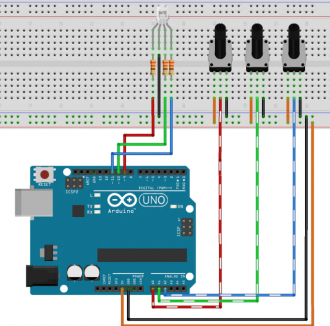
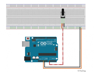
Now, connect the pot in the breadboard as shown. Moreover, connecting 5volts or GND at either terminal of Arduino does not matter. As the middle terminal is connected to the analog input pins, Hence, it is the most important connection over here.
And hence, 5Volts and GND is obtained from the Arduino pins.
Design of the circuit
The above process is repeated for three (3) pots for given colors.
For arranging neatly and in order, connect the red color Led to A0 pin, green color pin to A1, and Blue to A2.
Conventional LED (diode) concept is like that of RGB LED. The process occurs due to having 3 different colored LEDs next to each other. As the 3 LEDs are connected combinedly so are shown just like one led and when powered they luminate as single LED and hence, we see some mixed colors rising from one LED.
The value of each PWM output is 256. And the three pins that shows (Green, Red, Blue) have a total 16,777,216 colors i.e., 256*256*256. About 17 million.
As we connect any other simple LED, the same way we connected the RGB LED and just repeated this process 3 times.
The result must look like, we connect red value to the lower most pin on the input and output, just to make sure the things are simple, and to avoid complexity in code.
Remember to connect 330ohm resistor in breadboard.
CODE:
// the setup function runs once when you press reset or power the board
int inRGB[] = { A0,A1,A2 }; // Analog Inputs to reada potentiometer values
int outRGB[] = { 9,10,11 }; // PWM output pins to control brightness of each color in the RGB LED
int tempValue = 0; // Placeholder
const int inMinVal = 0, inMaxVal = 1023; // Values that define the maximum and minimum value returned from the potentiometer reading
void setup() {
// Loop on all pins ( 3 values: Red, Green and Blue )
for (int i = 0; i < 3; i++)
{
pinMode(inRGB[i], INPUT); // Prepare those pins to read the potentiometer values
pinMode(outRGB[i], OUTPUT); // Prepare those pins to output the values of the RGB LED
}
}
// the loop function runs over and over again until power down or reset
void loop() {
// Repeat the following for each color
for (int i = 0; i < 3; i++)
{
tempValue = analogRead(inRGB[i]); // Read the potentiometer
// Scale down the potentiometer reading ( 0 ~ 1023 ) to a valid PWM value
// 0 ~ 255 represent the range of the Arduino PWM output
tempValue = map(tempValue, inMinVal, inMaxVal, 0, 255);
// Write the output on the pin
analogWrite(outRGB[i], tempValue);
}
}
Conclusions
A simple project that mixes red, green, and blue with an RGB LED to make 7 colors. It is a simple project that uses an RGB LED to display different colors. It mixes the three primary colors (red, green, and blue) to make seven colors.
Where the potentiometer with built-in switch (off/on) is used to control the brightness of an RGB LED.
Future Work:
The user is greet up with the Color mixer page due to the selection of basic primary and secondary colors, after which the user can freely mix and match to their liking. You can choose your colors from the pre-existing shades offered on the website or add custom colors.
Other Projects of Arduino
-
Serial communication project using PIC microcontroller
-
Design of smart electronic voting machine using Arduino
-
How to control the speed and direction of DC motor using Arduino?
-
How to Display on 8×8 Dot Matrix LED Using Arduino(UNO)?
-
How to Design RGB Mood Lamp using Arduino?
-
Serial Temperature Sensor Project using Arduino
-
How to design an LED Flasher on Arduino Board
-
Design of Traffic Light Control system using Arduino
-
Arduino Project: How to control the speed of DC motor?
-
Arduino Project: Send Command with Serial Communication
-
Arduino Project: LED Fire Effect