what is the difference between data flow and behavioral modelling in Verilog HDL? This article will help you to get familiar with the dataflow and behavioral modelling of combinational circuits in Verilog HDL
What is dataflow modelling?
Dataflow modelling provides the means of describing combinational circuits by their function rather than by their gate structure.
Use:
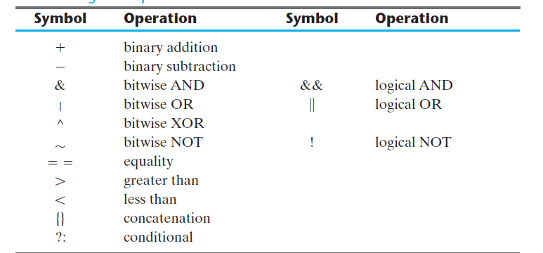
Dataflow modelling uses a number of operators that act on operands to produce the desired results. Verilog HDL provides about 30 operator types.
What are the Keywords in Verilog HDL?
Dataflow modeling uses continuous assignments and keyword to share. Continuous delivery is a value proposition net. The data network is used in Verilog HDL to represent physical connections between circuit components. The value assigned to the net is determined by the expression used by the operators and operators. For example, assuming a variant is announced, a 2-to-1 multiplexer with data input A and B, select input S, and output Y is defined for continuous function
give Y = (A & S) | (B & S)
The description of the data flow of the 2-to-4 line decoder is shown in HDL below. The region is defined by four continuous assignment statements using Boolean expressions, one for each output.
Description of data flow 2-to-4 line decoder with input module (E) module decoder (A, B, E, D); inputs A, B, E; output [3 ,: 0] D;
give D [3] = ~ (~ A & ~ B & ~ E); Or give D [3] = ~ (~ A & ~ B & ~ E), give D [2] = ~ (~ A & B & ~ E); D [2] = ~ (~ A & B & ~ E), give D [1] = ~ (A & ~ B & ~ E); D [1] = ~ (A & ~ B & ~ E), give D [0] = ~ (A & B & ~ E); D [0] = ~ (A & B & ~ E);
final module
Verilog HDL conditional operator takes three operators:
Status? real speech: false speech;
This operator is equivalent to if-else. The HDL provided below shows the definition of a 2-to-1 line multiplexer using conditional operators.
// Dataflow description for 2-to-1 line multiplexer line mux2x1_df (A, B, select, OUT); input A, B, select; output OUT; give OUT = select? A: B;
What is behavioral modeling in Verilog HDL?
Behavioral modeling represents digital circuits at an active and prepared level.
Use:
It is commonly used to describe consecutive circuits, but can also be used to define aggregate circuits. The concept of marketing ethics in the integration circuits will be introduced here.
Keyword:
The code of conduct uses a keyword that is always followed by a list of process allocation statements. The intended result of the
process allocation statement must be in the form of reg data. A description of the 2-to-1 line multiplexer behavior in HDL is provided below.
Moral Description:
Behavioral description of module 2x to 1 line multiplexer module mux2x1_bh (A, B, select, OUT); input A, B, select; output OUT; reg OUT;
always @ (select either A or B) if (select == 1) OUT = A; other OUT = B;
endmodule
Description:
Process distribution statements within the block are always made whenever there is a change in any of the variables specified behind the @ sign. In this case, it’s a variable to enter A, B, and select. The status statement if otherwise provides a decision based on the value of the selected input. If the statement can be written without the equation mark:
If (select) OUT = A;
HDL Description:
HDL definition of 4-to-1 line multiplexer is provided below. Selected input is defined as a2-bit vector and output y is declared as reg data. A permanent statement has a consecutive block inserted between the keyword and the endcase. The block is created whenever the input is calculated after the change in @ value. A case statement is a condition of a multi-conditional branch. The expression (select) is evaluated and compared with
the values listed in the following statements. The first value that matches the actual situation is made.
// Definition description of module 4-to-1 line of multiplexer mox4x1_bh (i0, i1, i2, i3, select, y);
inputs i0, i1, i2, i3; input [1: 0] select;
output y; reg y;
always @ (i0 or i1 or i2 or i2 or i3 or select) case (select)
2’b00: y = i0;
2’b01: y = i1;
2’b10: y = i2;
2’b11: y = i3; endcase
endmodule
BCD code:
Binary decoder (BCD) is a four-digit binary code for each digit 0 to 9 on a decimal number (base 10). A four-digit BCD code for any single basic single digit is represented in binary writing, as follows: 0 = 0000. 1 = 0001. 2 = 0010.
Excess 3 code:
1 combination of excess code-3 excess code 3 of 9 filling of the corresponding decimal number. For example, the code exceeds 3 of the decimal number 5 is 1000 and 1 corresponds to 1000 by 0111, which is a code over 3 by the decimal number 4, and is a 9-by the 5-by-number 5.
VHDL:
Hard Speed Integrated Circuit (VHSIC) Hardware Description Language (VHDL) is a language that describes the operation of electrical circuits, standard digital cycles. VHDL can be used to design hardware and build test organizations to ensure the functionality of that hardware. ..
HDL to VHDL:
VHSIC Hardware Definition Language (VHDL) is a hardware definition language (HDL) that can reflect the behavior and structure of digital systems at many levels of output, from program level to logical gateway, design entry, documentation, and verification purposes.
LABOR WORKING RELEASE WORK:
First job
1. Write a Verilog HDL description of the 2x to 1-line multiplexer data flow path.
2. Write with Verilog an HDL description of the behavior of the BCD-to-excess-3 converter.
Test Task
Decoder Dataflow Model
1. Enter the 2-to-4 decoder data flow description in Xilinx ISE 8.2i.
2. Write an HDL promotion module to emulate and validate the circuit.
3. On the Digilent S3 demo board, assign SW0-2 switches to input A, B and E respectively. Results will be allocated to LEDs,
LED0-3. For I / O pins located on the Digilent S3 board, see IO_pins.pdf or S3BOARD_rm.pdf.
4. Run the ISE synthesizer to get the circuit network list.
5. Start designing and editing FPGA. Make sure the circuit is working properly.
Multiplexer Dataflow model
Enter the 2x to-1 multiplexer data description of Xilinx ISE 8.2i, and write the HDL promotion module to mimic and validate the circuit.
C. Multiplexer rating behavior
1. Enter the 4-to-1 multiplexer behavior description in the ISE.
Also read here
What are the sequential programmable devices? Discuss any of them in detail