Introduction to state reduction
what is the state reduction and assignment in digital circuits? When we are designing a circuit having smaller number of inputs and outputs, we generally do not concern ourselves with the cost. Here we can use simplest techniques of state machine. However, in case of complex circuits, we need to keep cost and labor minimum while keeping the design accurate and stable. If we do not use those methods, we will easily be overwhelmed by the complexity of circuits. So, in order to reduce cost and complexity we use the techniques of state reduction and assignments.
State Reduction:
State reduction is the technique of eliminating those states by reducing the number of flip-flops which are equivalent in all aspects in a sequential circuits. The complexity of a circuit entirely depends on its number of states. So by reducing states complex circuits can be simplified.
Methods of State Reduction:
There are three methods of state reduction:
- Row Matching
- Implication Charts
- Successive Partitioning
what is row matching?
It is the easiest of the three, works well for state transition tables which in turn also have an obvious state and equivalent output for present state. This method do not give the simplified version for circuit but it is easy to use and fair results is the fair reason to use this method. In this method, it uses a world equity theorem: Si = Sj if and only if one input X, the results are the same and the following provinces are equal. All input sequence should be considered, but any information about the internal state of the system can be neglected. When using the theorem, both output and subsequent state must be extracted. However, only one input has a hypothetical input sequence. The typical method for recipe for reducing method:
Start with the state switch table
Identify the states with the similar output behavior.
If those countries change to the same situation that follows, they are equal.
Consolidate into one new and renamed state. Repeat until no new nations are included.
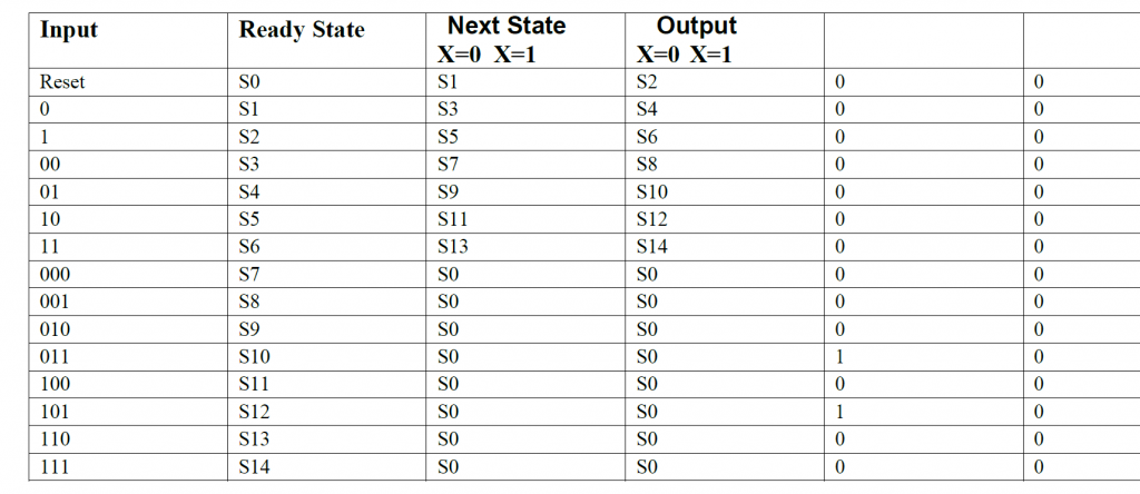
We can notice that S10 and S12 have same states as well same as output. These will merge together and will be new reduced state. Since S12 does not exist, all instance of S12 will be replaced by S10. So new table will be:
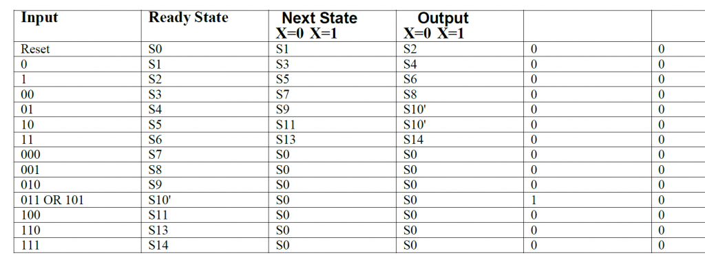
This process will go on until no new states can be recombined. The resulting reduced states will be:
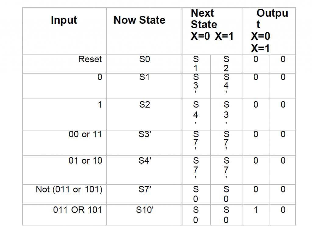
In this particular method we can see that the number of states were reduced to 7 from 15.
what is implication chart method?
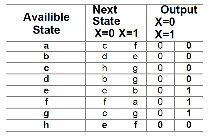
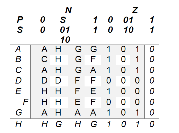
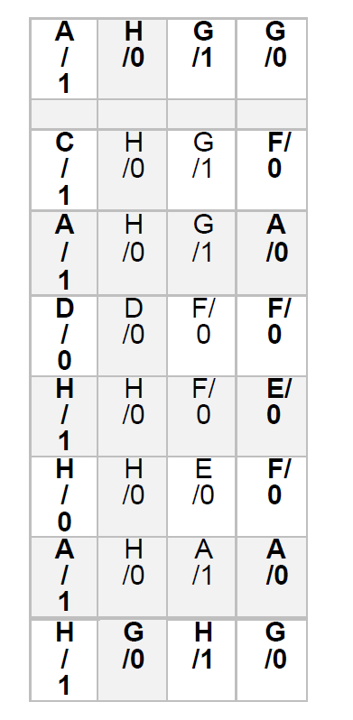
Implication charts are a common way to reduce FSM. It works by finding states that have the same transition with each other. It is a graphical method that can be easily calculated by hand. This method uses graphical grid sorts to evaluate equality among states. The implication charts helps in keeping track of implications. For example c-d and e-f are the pairs of implication for a-b according to given table:
The steps taken in this method are as follows:
Make an implication chart by taking one square for each state combination.
Squares will be labeled as Si and Sj, but if output are different than we get an
X. We can also write all the state pairs for inputs.
Now move through chart from left to right, similarly top to bottom.
Continue to follow step 3 until there is no square left with X.
what is successive partitioning?
It is a hybrid method between row matching and implication chart method. This method uses a visual detection method for equalizing as a charts to setup the whole process. The partitioning method gives simple procedure for reducing the complexity of the circuit. And successive partitions reduces the circuit into smaller partition and when partition cannot be done any further, then process is complete. All the equivalent states in same partition are equivalent.
Consider following example,
Now in order to start this reduction method we need to convert transition table into machine table for our own convenience.
Now the rows of the above machine table are state names while columns are state conditions. Now transfer the information into partition table.
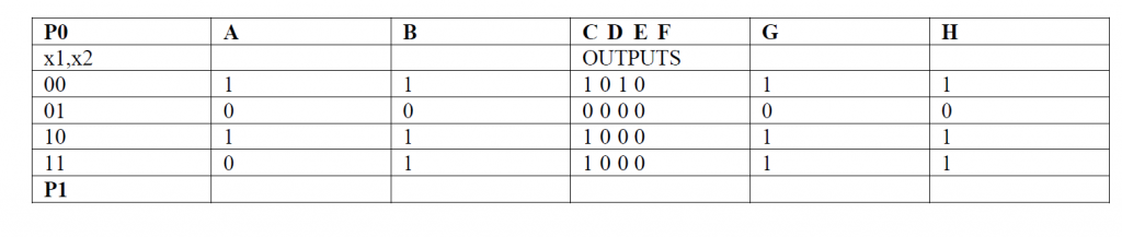
Now we need to find same output and place them in partition and record as P1 row. The next step will be to replace output with state names and check them to be partitioned. After various partitions the composite table is:
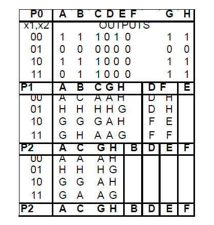
All the left grouped states are equivalent. Now we will put back the results in partitioning in state transition and state machine table.
Among these above methods, an engineer can use these to simplify circuits. Some methods will reduce number of states so it is better to try all methods before deciding one.
Now after reducing states next step is find state assignment which will simplify machine state more.
what is state assignment?
There are different ways for assigning states:
• Binary:
It is the most common method for assigning states. It start from 0 and continue to going up until 9 assigning each state with next number. It uses Log2 bit to assign states. Its is very common and easy method for assigning states. That’s why students learn binary method at first. But it is not that accurate, the bits are limited but encoding equation is much complex.
• Gray Code:
In Gray code every successive state differs by one bit. Since only one bit changes so power consumption is less than binary because in binary multiple states change at same time. This result in minimum number of bits and smaller and less complex equations.
But this only work if transfer of state is in order otherwise gray code does not work.
• One Hot Encoding:
This method uses registers for encoding. As much as register can be used. Within this method only one bit is One or Hot. All the remaining bits are 0. By this way it is make sure that only two bits change from moving one state to other. As only 2 bits changes the less power is consumed. It also reduces the logic needed to implement the gate. This method is used where large number of states need to be implemented.
Also read here
https://eevibes.com/digital-logic-design/draw-the-state-diagram-of-sequential-logic-circuits/