Introduction to Rectifiers
How many types of rectifiers are there? The rectifier changes over the ac input voltage to a pulsating dc voltage, called a half-wave rectified voltage. The filter disposes of the changes in the redressed voltage and produces a moderately smooth dc voltage. The regulator is a circuit that keeps a steady dc voltage for varieties in the info line voltage or in the heap. Regulators fluctuate from a solitary semiconductor gadget to more perplexing incorporated circuits. The heap is a circuit or gadget associated with the yield of the force supply and works from the force supply voltage and current.
The Half-Wave Rectifier
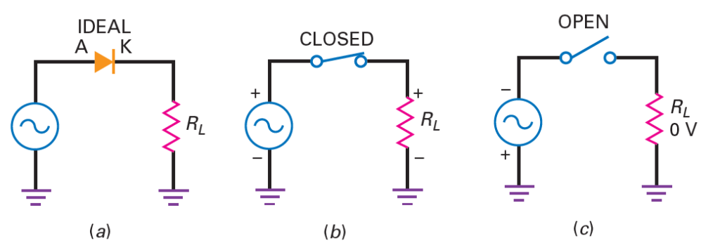
Following figure(a) shows a half-wave rectifier circuit. The ac source creates a sinusoidal voltage. Accepting an ideal diode, the positive half-pattern of source voltage will advance predisposition the diode. Since the switch is shut, as appeared in Fig.(b), the positive half-pattern of source voltage will show up across the heap resistor. On the negative half-cycle, the diode is converse one-sided. For this situation, the ideal diode will show up as an open switch, as appeared in Fig.(c), and no voltage shows up across the heap resistor.
Explain working of rectifiers?
The complete description of working of rectifiers is given below
Ideal Waveforms of half-wave rectifier
Following Figure(a) shows a graphical portrayal of the info voltage waveform. It is a sine wave with an immediate estimation of vin and a pinnacle estimation of Vp(in). A unadulterated sinusoid like this has a normal estimation of zero more than one cycle on the grounds that each immediate voltage has an equivalent and inverse voltage a large portion of a cycle later. On the off chance that you measure this voltage with a dc voltmeter, you will get a perusing of zero on the grounds that a dc voltmeter demonstrates the normal worth. In the half-wave rectifier of Fig.(b), the diode is leading during the positive half-cycles yet is nonconducting during the negative half-cycles. Since of this, the circuit cuts off the negative half-cycles, as appeared in Fig. (c). We call a waveform like this a half-wave signal. This half-wave voltage delivers a unidirectional burden current. This implies that it flows just a single way. On the off chance that the diode were switched, it would become forward one-sided when the info voltage was negative. Subsequently, the yield heartbeats would be negative. This is appeared in Fig. (d).
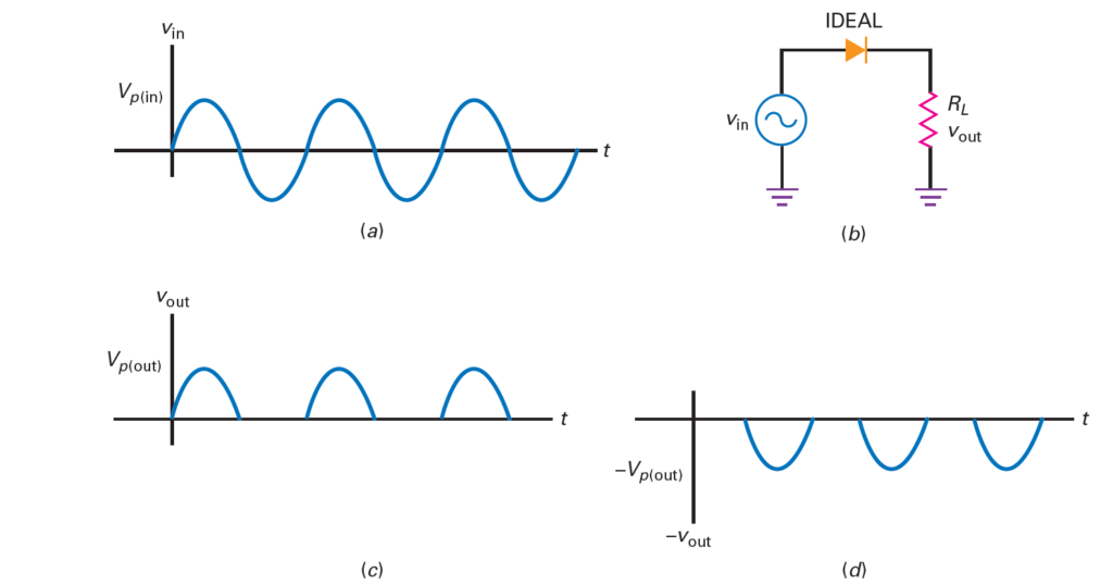
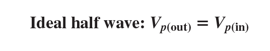
Notice how the negative pinnacles are counterbalanced from the positive pinnacles and follow the negative rotations of the input voltage. A half-wave signal like the one in Fig. 4-2c is a pulsating dc voltage that increments to a most extreme, diminishes to zero, and afterward stays at zero during the negative half-cycle. This isn’t the sort of dc voltage we need for hardware gear. explain working of rectifiers. What we need is a consistent voltage, equivalent to you get from a battery. To get this sort of voltage, we need to filter the half-wave signal (examined later in this part). At the point when you are investigating, you can utilize the ideal diode to dissect a half-wave rectifier. It’s helpful to recall that the pinnacle yield voltage approaches the top information voltage:
Ripple factor Derivation for Half-Wave or Full-Wave Rectifier
DC Value of Half-Wave Signal
The dc estimation of a sign is equivalent to the normal worth. In the event that you measure a sign with a dc voltmeter, the perusing will rise to the normal worth. In fundamental courses, the dc estimation of a half-wave signal is determined. The equation is:
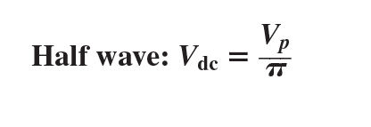
The verification of this determination requires math since we need to work out the normal incentive more than one cycle.
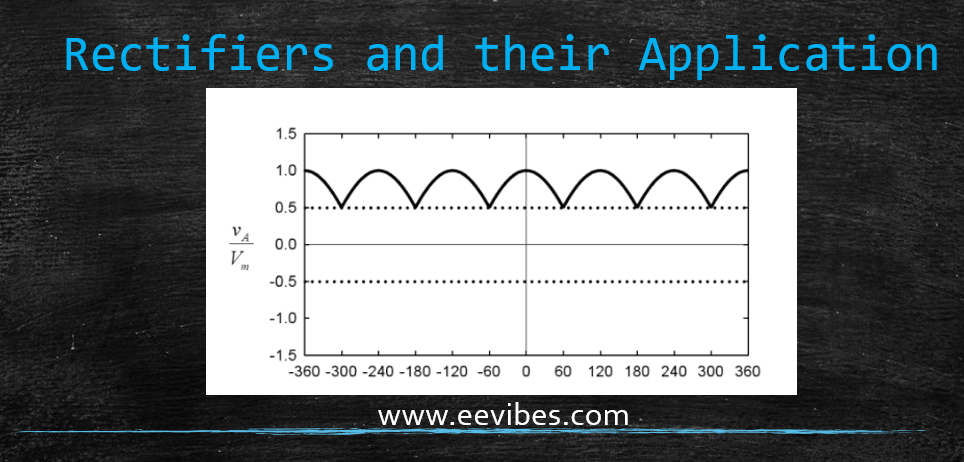
At the point when the condition is written in this structure, you can see that the dc or normal worth rises to 31.8 percent of the pinnacle esteem. For example, if the pinnacle voltage of the halfwave signal is 100 V, the dc voltage or normal worth is 31.8 V.
Derivation of Average Value of Output Voltage of Half-wave Rectifier
Output Frequency
The yield recurrence is equivalent to the info recurrence. This bodes well when you analyze previous Fig. (c) with Fig. (a). Each pattern of information voltage produces one pattern of yield voltage. Subsequently, we can compose:
output frequency=input frequency
We will utilize this inference later with filters.
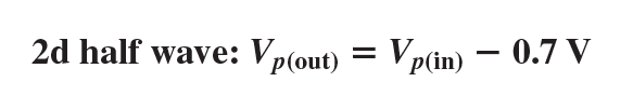
Second Approximation
We don’t get an ideal half-wave voltage across the heap resistor. In view of the obstruction potential, the diode doesn’t turn on until the air conditioner source voltage comes to roughly 0.7 V. At the point when the pinnacle source voltage is a lot more noteworthy than 0.7 V, the heap voltage will take after a half-wave signal. For example, if the pinnacle source voltage is 100 V, the heap voltage will be near an ideal half-wave voltage. In the event that the pinnacle source voltage is just 5 V, the heap voltage will have a pinnacle of just 4.3 V. At the point when you need to improve answer, utilize this deduction:
Higher Approximations
Most originators will ensure that the mass obstruction is a lot more modest than the Thevenin opposition confronting the diode. Along these lines, we can overlook mass obstruction in pretty much every case. On the off chance that you should have preferred precision over you can get with the subsequent estimation, you should utilize a PC and a circuit test system like Multisim.
What value of filter capacitor is required to produce a 1% ripple factor for a full-wave rectifier having a load resistor of 1.5k ? Assume the rectifier produces a peak output voltages of 18V.
A certain rectifier filter produces a dc output voltage of 75V with a peak-to-peak ripple voltage of 0.5V. Calculate the ripple factor.
A certain full-wave rectifier has a peak output voltage of 30V. A 50µF capacitor-input filter is connected to the rectifier. Calculate the peak-to-peak ripple and dc output voltage developed across a 600Ω load resistance.
A full-wave rectifier produces an 80V peak rectified voltage from a 60Hz ac source. If a 10µF capacitor is used, determine a ripple factor for a load resistance of 10k.
Also read here:
https://eevibes.com/diode-a-nonlinear-device-and-its-applications/
2 thoughts on “What are the Rectifiers? Types of Rectifiers”