Table of Contents
Diode: A Non Linear Semiconductor Device
In this article, readers will come to know why the diode is considered as a non-linear device. As we all know diode: a non linear semiconductor device that is used to conduct the current in only one direction. Its the basic circuit element in electronics (where we study the controlled motion of electrons). It is designed using two semiconductor materials: p-type and n-type. The junction where these two material intersect is called the pn junction. The other name of pn junction is depletion region as it is depleted of free electrons.
How conduction occurs in diode?
There are two ways to bias the diode: forward bias and reverse bias. In reverse biasing the positive terminal of the battery is connected with the n-type and the negative terminal of the battery is connected with the p-type. There is no conduction current in this case. Only current that flows is the leakage current that is because of minority charge carriers. It is of the order if micro amperes. In this case the internal resistance of the diode is very high as width of the depletion region increase with more reverse biasing voltages. If you keep increasing the reverse bias voltages then there comes a time when an abrupt amount of current will flow through the diode. This phenomenon is called breakdown and the voltages at which this happens is called the ‘breakdown voltages‘.
when the diode is connected such that the positive terminal of the battery is connected with the p-side and the negative side is connected with n-side it is called forward biasing. In forward biasing diode conducts current of the order of milliampere. In this case the internal resistance of the diode is very small. The current flowing in this case is because of majority charge carriers. It is given as:
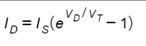
Here Vd are diode biased voltages, VT are the thermal voltages, Is is the saturation current, and ID is the amount of current that flows through diode on biased voltages.
Solve a Circuit using Ideal Diode Current Equation
Now as we all know that any device that has direct relation of its current with its voltages is called a linear device or ohmic device. In simple words, if a device follows ohm’s law then it is called a linear device otherwise a non-linear. For better understanding lets have look at VI characteristics of general purpose diode.
Ideal Diode Equation
In this video I have solved an example using the ideal diode equation.
What is the Value of Thermal Voltages at Room Temperature?
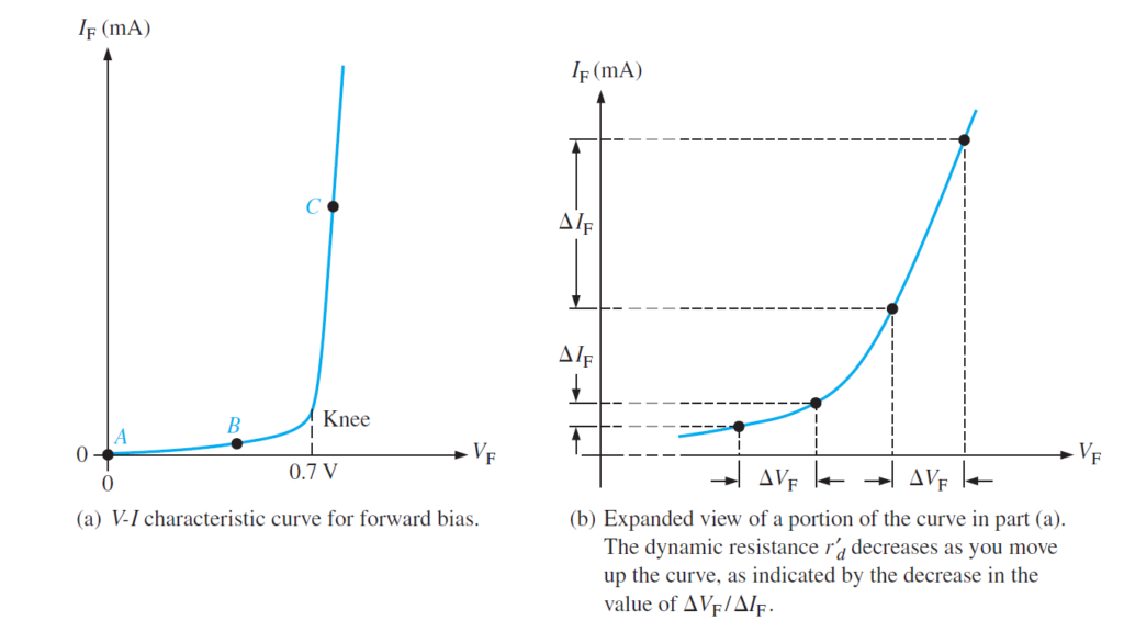
If you plot the graph of the observations of the following circuit you get the V-I characteristics for a forward biased diode on right side, as appeared in the figure above. The diode forward voltage (VF) increases to one side up to the knee point, and the forward current (IF) increments upward along the vertical axis. As you can see in Figure , the forward current increases almost to very small amount until the forward voltage across the pn junction reaches at roughly 0.7 V at the knee of the curve After this point, the forward voltage remains almost consistent at around 0.7 V, however IF increments quickly. As recently referenced, there is a slight increase in VF above 0.7 V as the current increments due to the voltage drop across the dynamic resistor. The IF scale is normally in mA, as demonstrated. Three focus points A, B, and C are appeared on the bend in the above figure. Point A relates to a zero-slope condition. Point B is the point where the forward voltage is not exactly the barrier potential of 0.7 V. Point C is the point where the forward voltage around approaches the barrier potential. As the external supply voltages increases, forward current keeps on increasing over the knee, the forward voltage will increment somewhat above 0.7 V. Actually, the forward voltage can be as much as roughly around 1V.
Dynamic Resistance showing diode: a non linear semiconductor device
Above figure shows an extended perspective on the V-I trademark bend to some degree (a) and shows dynamic resistance. In contrast to a direct obstruction, the opposition of the forward-one-sided diode isn’t steady over the whole bend. Since the opposition changes as you move along the V-I bend, it is called dynamic or ac obstruction. Inward protections of electronic gadgets are generally assigned by lowercase italic r with a prime, all things considered of the standard R. The dynamic opposition of a diode is assigned Beneath the knee of the bend the opposition is most noteworthy in light of the fact that the current increments very little for a given change in voltage The opposition starts to diminish in the district of the knee of the bend and gets littlest over the knee where there is a enormous change in current for a given change in voltage.
V-I Characteristic for Reverse Bias
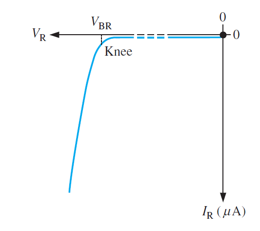
At the point when a converse predisposition voltage is applied across a diode, there is just a tiny opposite current (IR) through the pn intersection. With 0 V across the diode, there is no opposite current. As you steadily increment the opposite inclination voltage, there is a little converse current and the voltage across the diode increments. At the point when the applied inclination voltage is expanded to a worth where the opposite voltage across the diode (VR) arrives at the breakdown esteem (VBR), the opposite current starts to increment quickly. As you keep on expanding the predisposition voltage, the current keeps on expanding quickly, in any case, the voltage across the diode increments next to no above VBR. Breakdown, with special cases, is certifiably not an ordinary method of activity for most pn intersection gadgets. Charting the V-I Curve If you plot the aftereffects of converse predisposition estimations on a diagram, you get the V-I trademark bend for an opposite one-sided diode. An average bend is appeared in figure. The diode turn around voltage (VR) increments to one side along the flat pivot, what’s more, the opposite current (IR) increments descending along the vertical pivot. There is next to no opposite current (generally ) until the converse voltage across the diode arrives at around the breakdown esteem (VBR) at the knee of the bend. After this point, the converse voltage stays at roughly VBR, however IR increments quickly, coming about in overheating and conceivable harm if current isn’t restricted to a protected level. The breakdown voltage for a diode relies upon the doping level, which the producer sets, contingent upon the kind of diode. An average rectifier diode (the most generally utilized sort) has a breakdown voltage of more prominent than 50 V. Some particular diodes have a breakdown voltage that is just 5 V.
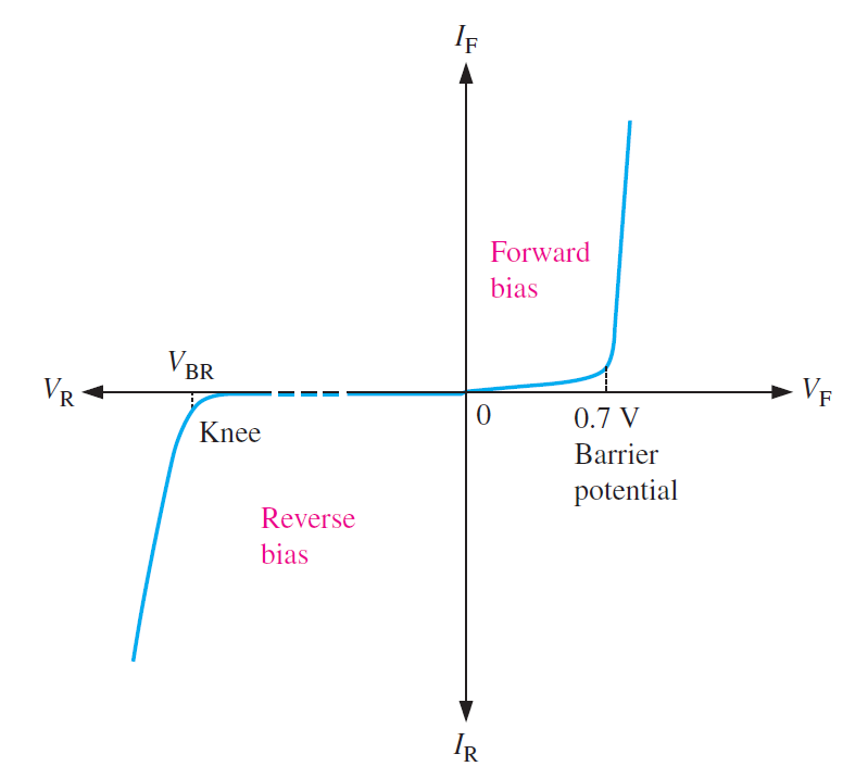
The Complete V-I Characteristic Curve
Join the bends for both forward inclination and opposite predisposition, and you have the total V-I
trademark bend for a diode, as appeared in Figure below
Also read here
- How Tunnel diode works?
- What are the diode models? Ideal, practical and complete models with examples
- What are the switching circuits of diode? Examples and Problems
- How to test a diode? When diode is working and when it is not working?
- How zener diode is used for voltage and line regulation?
- What is the varactor diode and how does it work?
- what is the difference between drift and diffusion current of a diode?
- What is the light emitting diode (LED)? How does it work?
- What is the barrier potential of PN junction diode ?
3 thoughts on “Diode as a Non-Linear Device: Ideal Diode Current Equation”